Ignition system and method for operating an ignition system

a technology of ignition system and ignition system, which is applied in the direction of engine ignition, ignition control, machines/engines, etc., can solve the problems of reducing the installation space conditions of modern engine concepts, and achieve the effect of cost-effective, cost-effective, and sufficient accuracy

Inactive Publication Date: 2016-10-27
ROBERT BOSCH GMBH
View PDF25 Cites 8 Cited by
  • Summary
  • Abstract
  • Description
  • Claims
  • Application Information

AI Technical Summary

Benefits of technology

[0003]The aforementioned object is achieved according to the present invention by a method for operating an ignition system for an internal combustion engine, including a boost converter. The present invention in this case provides for detecting a spark breakaway prior to or during the use of the boost converter and modifying the operating mode of the boost converter in response thereto. In other words, it is checked whether a spark breakaway has taken place and if a spark breakaway has occurred, the voltage generated at the boost converter is modified. Since the output voltage of the boost converter increases as a result of a spark breakaway, the output voltage of the boost converter in the case of ideal components without protective circuitry would increase to the point of the boost converter self-destructing. The above described scenario is avoided by suitably modifying the operating mode of the boost converter, for example, by switching off or reducing the generation of an output voltage of the boost converter.
[0007]In one refinement, the method may also include a measurement of a spark current in a loop of the spark gap. In other words, a current is measured, which allows a conclusion to be drawn about a potential breakaway of the ignition spark. The spark breakaway is detected in response to an undercutting of a threshold value of the spark current. In this case, a predefined current value may be stored as a reference and retrieved in order to compare the measured value with the reference. The current measurement may be relatively precisely and cost-effectively carried out through mediation of hardware already included in ignition systems, so that the present invention may be implemented in a particularly cost-effective manner. Alternatively, a conclusion may be drawn about the level of the spark current via a voltage measurement. A defined output is delivered by the operation of the boost converter. Thus, current and voltage are in a fixed relationship to one another.
[0008]The spark current may be further measured via a shunt, which is located in a loop with a spark gap of the ignition system. The shunt in this case may also be used to ascertain a control variable for the operating mode of the boost converter (for example, its frequency). The measurement with the aid of the shunt traces the current measurement back to a voltage measurement, so that a reference for ascertaining a spark breakaway may also be stored as a voltage value and provide the basis of a comparison. Electrical circuitry or analog circuits or microcontroller or ASICs frequently found in ignition systems may represent a cost-effective option for ascertaining a voltage with sufficient accuracy. This enables a cost-effective implementation of the present invention.

Problems solved by technology

This conflicts with the reduced installation space conditions of modern engine concepts (“downsizing”).

Method used


Image

  • Ignition system and method for operating an ignition system
  • Ignition system and method for operating an ignition system
  • Ignition system and method for operating an ignition system

Examples


Embodiment Construction

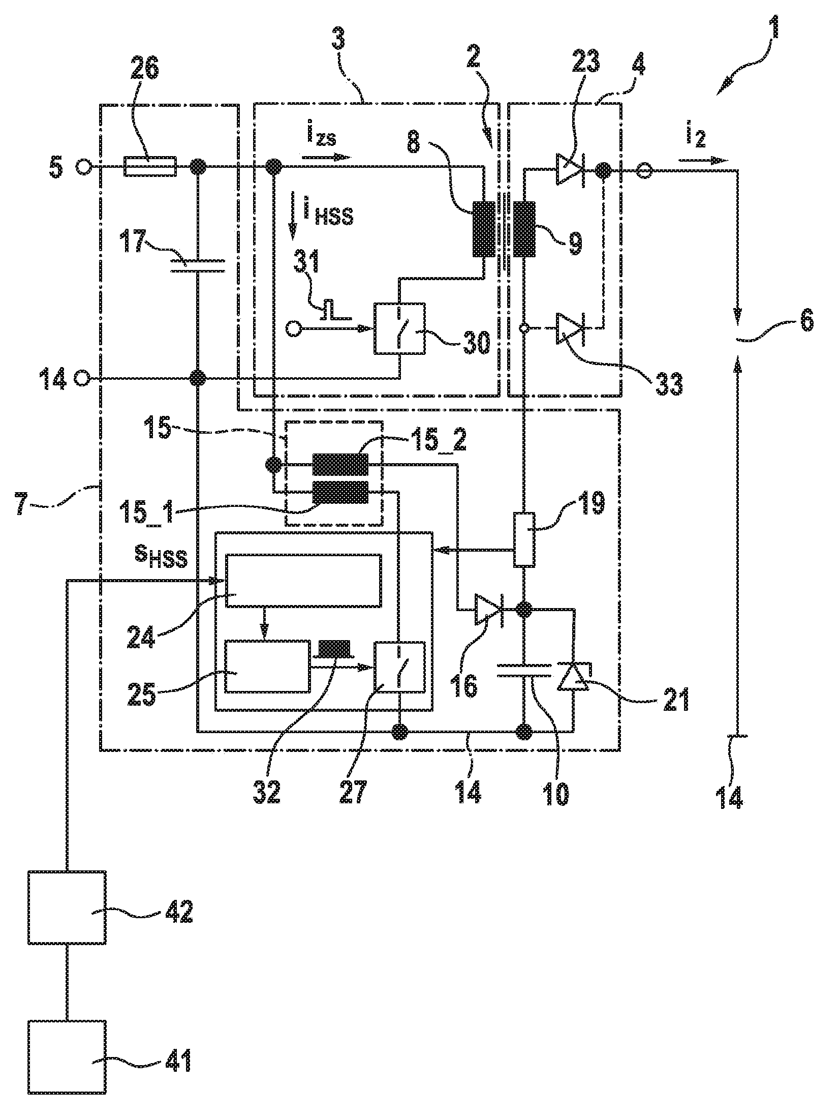
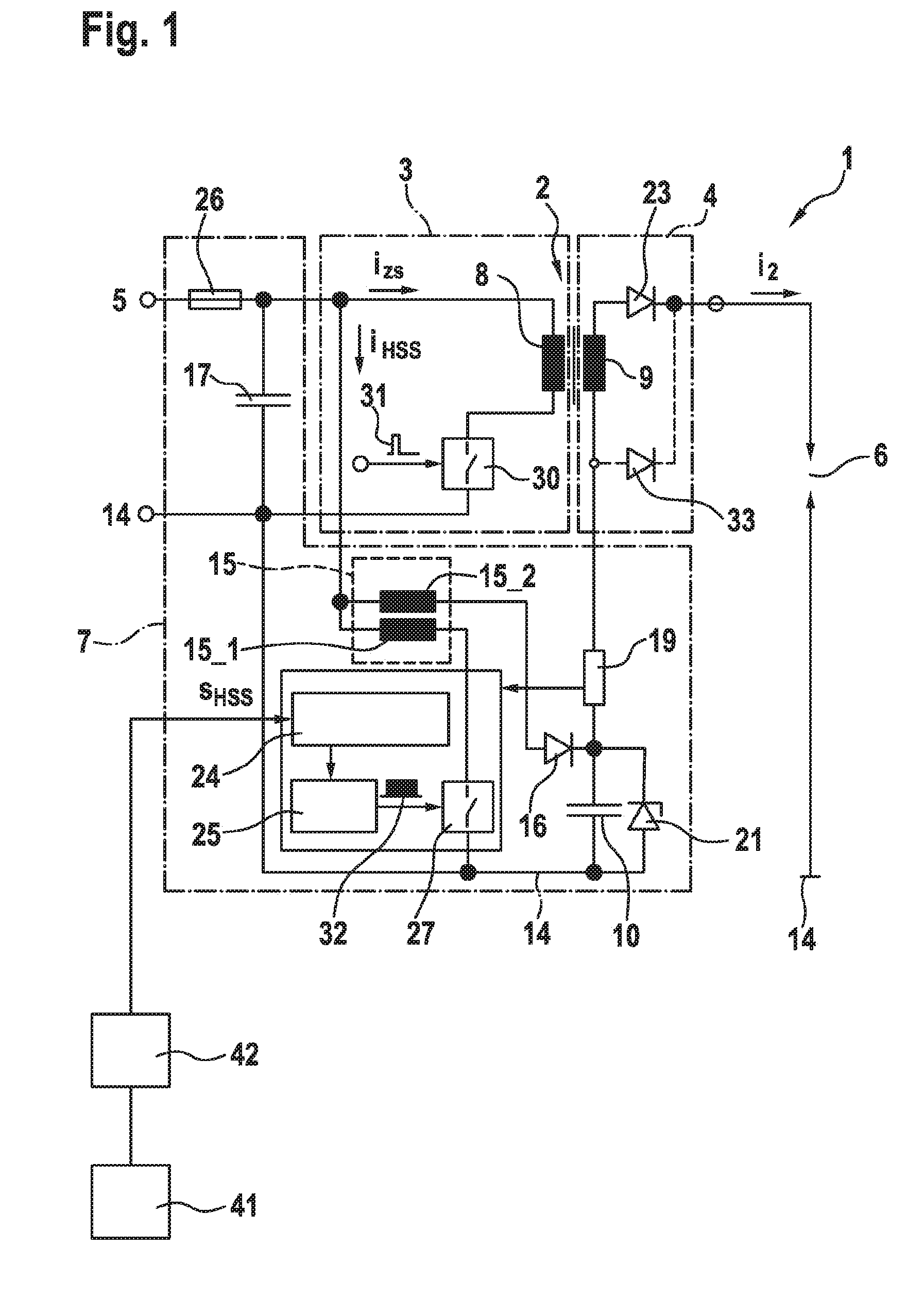
[0020]FIG. 1 shows a circuit of an ignition system 1, which includes a step-up transformer 2 as a high voltage generator, the primary side 3 of which may be supplied with electrical energy from an electrical energy source 5 via a first switch 30. Step-up transformer 2 includes, for example, a primary coil 8 and a secondary coil 9. A fuse 26 is provided at the input of the circuit, in other words, therefore, at the terminal to electrical energy source 5. In addition, a capacitance 17 for stabilizing the input voltage is provided in parallel to the input of the circuit or in parallel to electrical energy source 5. Secondary side 4 of step-up transformer 2 is supplied with electrical energy via an inductive coupling of primary coil 8 and secondary coil 9, and includes a diode 23 known from the related art for suppressing the powering spark, this diode 23 being alternatively substitutable with diode 21. A spark gap 6, via which ignition current i2 is intended to ignite the combustible g...


PUM


Abstract

A method for operating an ignition system for an internal combustion engine is described, including a boost converter, characterized by a detection of a spark breakaway and, in response thereto, a modification of the operating mode of the boost converter. An ignition system for an internal combustion engine is also described, including a boost converter, which includes an arrangement for carrying out the aforementioned method.

Description

FIELD OF THEN INVENTION[0001]The present invention relates to a method for operating an ignition system for an internal combustion engine. In addition, the present invention relates to a corresponding ignition system. The present invention relates, in particular, to an avoidance of unstable operating states of such an ignition system.BACKGROUND INFORMATION[0002]Ignition systems are known in the related art for spark-igniting ignitable mixtures in combustion chambers of internal combustion engines. A spark gap within the combustion chamber is acted on with such a voltage that a spark discharge takes place, which ignites the mixture. The main requirements of modern ignition systems are an indirect result of necessary emission and fuel reductions. Requirements of ignition systems and their spark (energies) are derived from corresponding engine-related approaches such as supercharging and lean operation and shift operation (spray-guided direct injection) in combination with increased ex...

Claims


Application Information

Patent Timeline
Patent Type & Authority Applications(United States)
IPC IPC(8): F02P9/00F02P17/12
CPCF02P17/12F02P9/007F02P15/10
Inventor SKOWRONEK, TIMPAWLAK, THOMASSINZ, WOLFGANG
Owner ROBERT BOSCH GMBH
Why Eureka
Try Eureka