Eureka AIR delivers breakthrough ideas for toughest innovation challenges, trusted by R&D personnel around the world.

Spectroscopic measurement apparatus

a spectroscopic measurement and apparatus technology, applied in the direction of optical radiation measurement, instruments, spectrometry/spectrophotometry/monochromators, etc., can solve the problems of difficult high-speed measurement, limited number of data obtained per unit time, and apparatus getting to be expensive, so as to achieve the effect of inexpensive configuration

Active Publication Date: 2016-10-27
HAMAMATSU PHOTONICS KK
View PDF3 Cites 6 Cited by
  • Summary
  • Abstract
  • Description
  • Claims
  • Application Information

AI Technical Summary

Benefits of technology

The present invention aims to provide a spectroscopic measurement apparatus that can perform high-speed measurement with an inexpensive configuration. This means that the apparatus can speed up the measurement process while using affordable components.

Problems solved by technology

However, due to the property of a laser light source used as a light source, the number of data obtained per unit time is limited.
Since it is necessary to perform measurement for a long time in order to increase the number of data, it is difficult to perform high-speed measurement.
Since it is necessary to use many detectors to obtain the detailed absorption information on the measurement sample, the apparatus gets to be expensive.
However, since it is necessary to sequentially switch many bandpass filters, it is difficult to perform high-speed measurement.
An apparatus disclosed in Patent Document 2 is for identifying a tooth color based on spectroscopic characteristics of teeth, and by using a filter having loss characteristics according to the spectroscopic characteristics in the measurement sample (teeth), the color of the measurement sample (tooth) is classified from light intensity measurement data measured a few times. However, it is difficult to product the filter according to the measurement sample, and also, there is a possibility that the apparatus becomes expensive.

Method used


Image

  • Spectroscopic measurement apparatus
  • Spectroscopic measurement apparatus
  • Spectroscopic measurement apparatus

Examples


Embodiment Construction

[0048]Embodiments of the present invention will be described in detail below with reference to the attached drawings. In the description on the drawings, the same elements will be denoted with the same reference symbols, and overlapping description will be omitted.

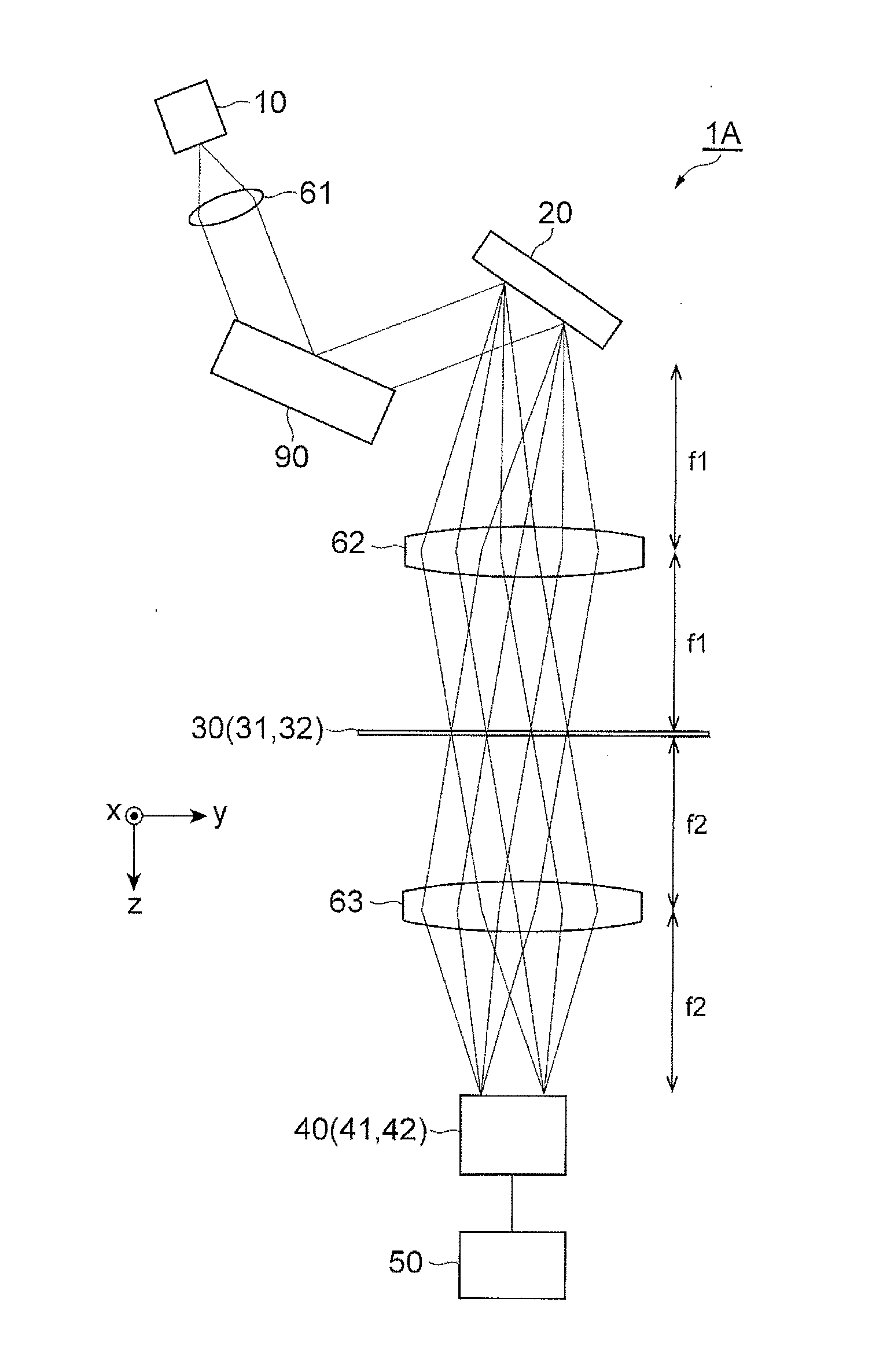
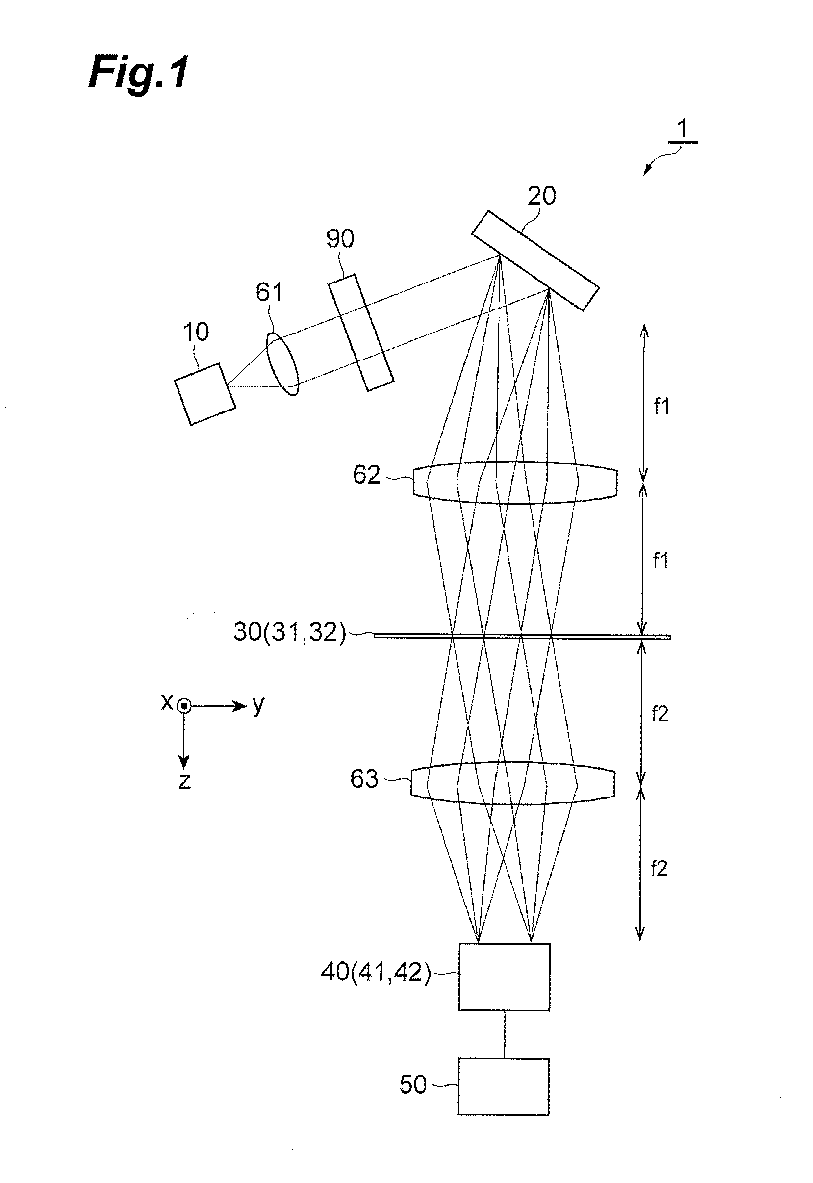
[0049]FIG. 1 to FIG. 3 are diagrams of a configuration of a spectroscopic measurement apparatus 1 according to the present embodiment. For convenience of the description, a xyz orthogonal coordinate system is illustrated in these figures. The spectroscopic measurement apparatus 1 includes a light source 10, a diffraction grating 20, a spatial filter unit 30, a detection unit 40, an analysis unit 50, a lens 61, a cylindrical lens 62, and a cylindrical lens 63, and spectroscopically measures a measurement sample 90 arranged on an optical path between the light source 10 and the detection unit 40.

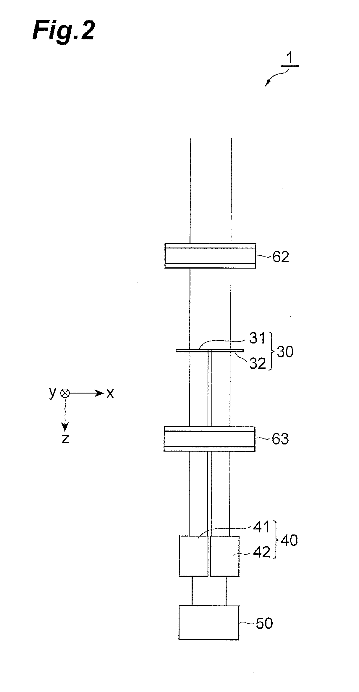
[0050]FIG. 2 is a side view of a part of the configuration of the spectroscopic measurement apparatus 1 according to the present em...


PUM


Abstract

A spectroscopic measurement apparatus includes a light source, a diffraction grating being a spectroscopic unit, a spatial filter unit, a detection unit, and an analysis unit. The diffraction grating spatially disperses light from the light source, and outputs the light to different optical paths according to a wavelength. The spatial filter unit inputs the light from the diffraction grating to different positions according to the wavelength, applies loss depending on the wavelength to the light, and outputs the light. The detection unit detects the intensity of the light from the spatial filter unit. The analysis unit obtains the intensities of light in an absorption band and light in a non-absorption band of a component in a measurement sample on an optical path between the light source and the detection unit based on the detection result, and evaluates the component in the measurement sample.

Description

BACKGROUND OF THE INVENTION[0001]1. Field of the Invention[0002]The present invention relates to a spectroscopic measurement apparatus.[0003]2. Related Background Art[0004]In an infrared range, in particular, a region having a wavelength of 2.5 to 25 μm is referred to as a fingerprint region, and an absorption peak specific to a substance appears in the region, therefore, the region is used to identify the substance. When absorption characteristics of the substance in the infrared range are measured, Fourier transform infrared spectroscopy (FTIR) technique is mainly used.[0005]In the FTIR, a measurement sample is arranged on one optical path of two optical paths in an interference optical system, and an optical path length difference between the two optical paths is scanned so that interference intensity data is obtained in time series, and by performing Fourier transform to the time series data, absorption information on the measurement sample in each wavelength is obtained. For th...

Claims


Application Information

Patent Timeline
Patent Type & Authority Applications(United States)
IPC IPC(8): G01J3/02G01J3/42
CPCG01J3/42G01J3/0229G01J2003/1213G01N2021/3595
Inventor KAWADA, YOICHISHIMIZU, YOSHIYUKIYAMAUCHI, TOYOHIKO
Owner HAMAMATSU PHOTONICS KK
Why Eureka
Eureka Blog
Learn More