Circuit board and method for manufacturing the same

Active Publication Date: 2016-10-27
UNIMICRON TECH CORP
View PDF6 Cites 19 Cited by
  • Summary
  • Abstract
  • Description
  • Claims
  • Application Information

AI Technical Summary

Benefits of technology

The present invention provides a circuit board that includes a heat-storing device and a thermoelectric device embedded in a substrate. The heat-storing device converts the thermal energy generated by the processor into electrical energy. This way, the waste heat generated by the processor can be efficiently utilized. Additionally, the thermoelectric device converts the stored thermal energy into electrical energy after the operation of the processor is finished and supplies it to other elements that are still operating. This circuit board serves as a heat-recovery device that helps to maintain the optimal temperature of the processor.

Problems solved by technology

With an enhancement of computer performance, the power of the computer has been increased, and therefore a problem of waste heat accumulated in the computer has become more obvious.
However, the heat sink just carries the thermal energy generated by the processor out.
That is, the heat sink does not have the properties which might enable it to handle the thermal energy potential which has been gathered by the waste heat.

Method used


Image

  • Circuit board and method for manufacturing the same
  • Circuit board and method for manufacturing the same
  • Circuit board and method for manufacturing the same

Examples


first embodiment

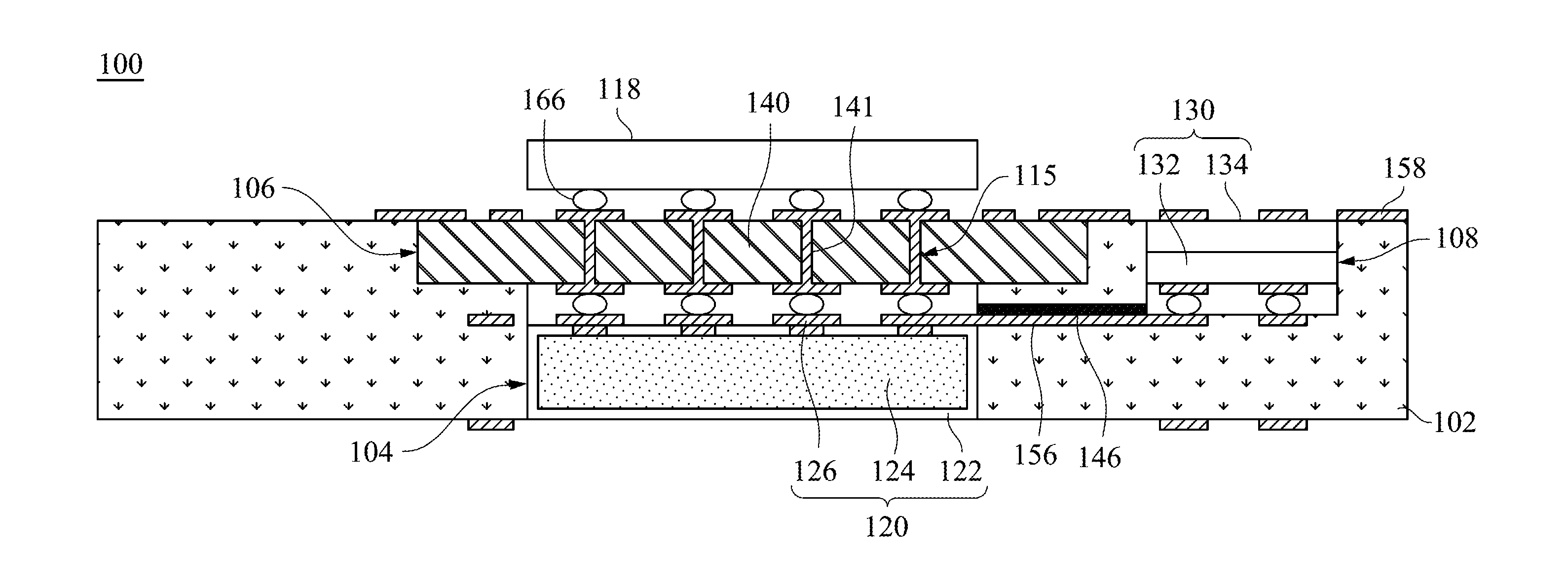
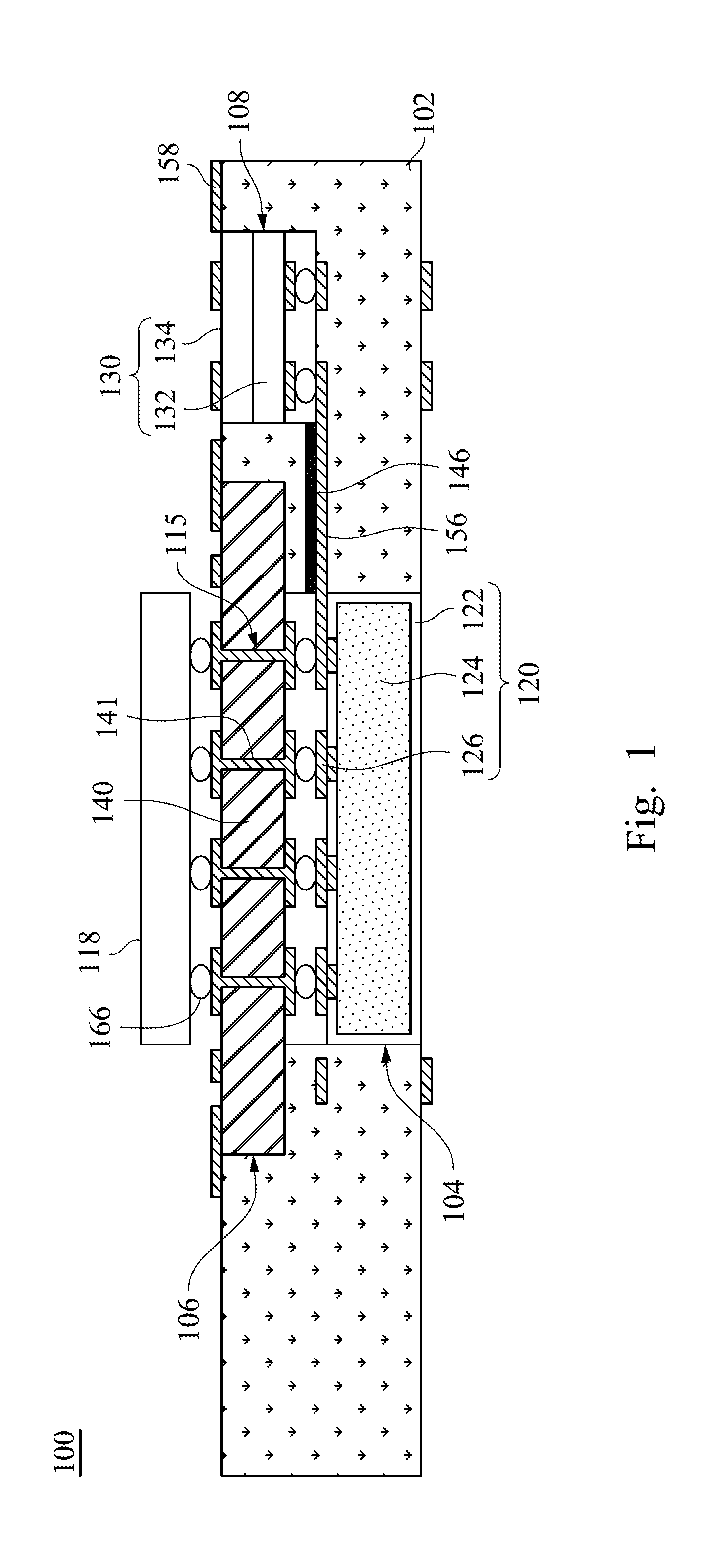
[0026]FIG. 1 is a schematic side view according to a circuit board 100 of this invention. A circuit board 100 with a heat-recovery function includes a substrate 102, a heat-storing device 120, and a thermoelectric device 130. The heat-storing device 120 is embedded in the substrate 102 and connected to a processor 118 for performing heat exchange with the processor 118. The thermoelectric device 130 embedded in the substrate 102 includes a first metal-junction surface 132 and a second metal-junction surface 134. The first metal-junction surface 132 is connected to the heat-storing device 120 for performing heat exchange with the heat-storing device 120. The second metal-junction surface 134 is joined with the first metal-junction surface 132, in which the thermoelectric device 130 generates an electric potential by a temperature difference between the first metal-junction surface 132 and the second metal-junction surface 134.

[0027]In the present embodiment, the processor 118 may be ...

third embodiment

[0053]In the present embodiment, a heat-conducting path is arranged in the vertical direction. However, according to a relationship between the positions of the circuit board 100 and the elements supplied the electrical energy by the thermoelectric device 130, a person having ordinary skill in the art may choose the proper arrangement of the circuit board 100 with the first, the second, or the

[0054]The circuit board 100 further includes a fixing frame 144. The fixing frame 144 is disposed in the second recess 112, in which the heat-storing device 120 is located in the fixing frame 144. The heat-storing device 120 further includes a third recess 114, in which the processor 118 is located in the third recess 114. The surfaces of the substrate 102, the fixing frame 144, the heat-storing device 120, and the processor 118 are coplanar. In other words, the fixing frame 144, the heat-storing device 120, and the processor 118 of the present embodiment are embedded in the substrate 102. More...


PUM


Abstract

A circuit board with a heat-recovery function includes a substrate, a heat-storing device, and a thermoelectric device. The heat-storing device is embedded in the substrate and connected to a processor for performing heat exchange with the processor. The thermoelectric device embedded in the substrate includes a first metal-junction surface and a second metal-junction surface. The first metal-junction surface is connected to the heat-storing device for performing heat exchange with the heat-storing device. The second metal-junction surface is joined with the first metal-junction surface, in which the thermoelectric device generates an electric potential by a temperature difference between the first metal-junction surface and the second metal-junction surface.

Description

BACKGROUND[0001]1. Field of Invention[0002]The present invention relates to a circuit board. More particularly, the present invention relates to a circuit board with a heat-recovery function.[0003]2. Description of Related Art[0004]With an enhancement of computer performance, the power of the computer has been increased, and therefore a problem of waste heat accumulated in the computer has become more obvious. In order to make the operations of the computer perform more smoothly, a heat-dissipation structure is generally disposed on a processor of the computer. The waste heat accumulated in the processor can be transmitted from the processor to the outside by the heat-dissipation structure so as to prevent a system crash due to overheating caused by the waste heat accumulated in the processor.[0005]The heat-dissipation structure commonly used nowadays is a heat sink, in which the heat sink can carry a thermal energy generated by the processor out by convection. However, the heat sin...

Claims


Application Information

Patent Timeline
IPC IPC(8): H05K1/18H05K1/11H01L35/30H05K3/30H05K3/40H05K1/02H05K3/46
CPCH05K1/185H05K1/0206H05K1/111H05K1/115H05K2201/10219H05K3/4697H05K3/30H05K3/4038H01L35/30H05K3/4647H05K1/187H01L23/13H01L23/4275H01L2224/16227H01L2224/16235H01L2924/15153H01L2924/15313H01L23/49827H05K2201/10378H05K2201/10734H10N10/13G06F1/206H05K1/0203H05K1/181H05K1/113H05K2201/048H05K2201/10515H01L23/12H01L2224/16225
Inventor CHEN, YIN-JUWU, MING-HAOYU, CHENG-PO
Owner UNIMICRON TECH CORP
Why Eureka
Try Eureka