Slide Guide Unit And Surveying Instrument

Active Publication Date: 2016-11-03
KK TOPCON
View PDF11 Cites 4 Cited by
  • Summary
  • Abstract
  • Description
  • Claims
  • Application Information

AI Technical Summary

Benefits of technology

The present invention is about a new slide guide unit that prevents the slider and the slider support part from being loose, which can happen when using the slide guide with a surveying instrument. The aim is to improve the accuracy of the surveying and make it more reliable.

Problems solved by technology

However, when there is a looseness between the slider and a slider support portion which supports the slider, the displacement given by the actuator is not accurately transmitted to the slider and an error occurs.

Method used


Image

  • Slide Guide Unit And Surveying Instrument
  • Slide Guide Unit And Surveying Instrument
  • Slide Guide Unit And Surveying Instrument

Examples


Embodiment Construction

[0026]A description will be given below on an embodiment of the present invention by referring to the attached drawings.

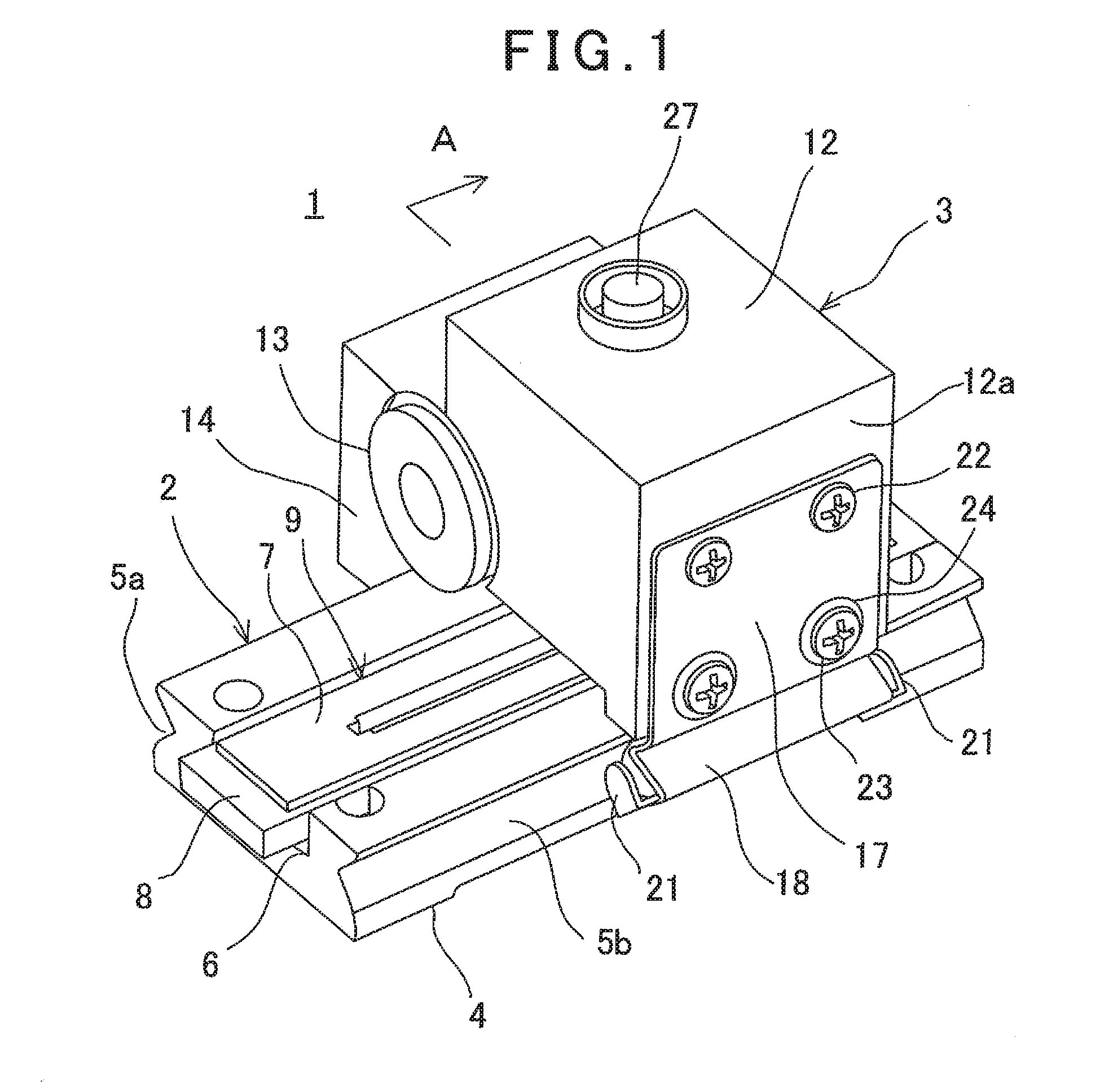
[0027]A description will be given on a slide guide unit 1 according to an embodiment of the present invention by referring to FIG. 1 to FIG. 5.

[0028]The slide guide unit 1 comprises a guide unit 2 and a slider unit 3.

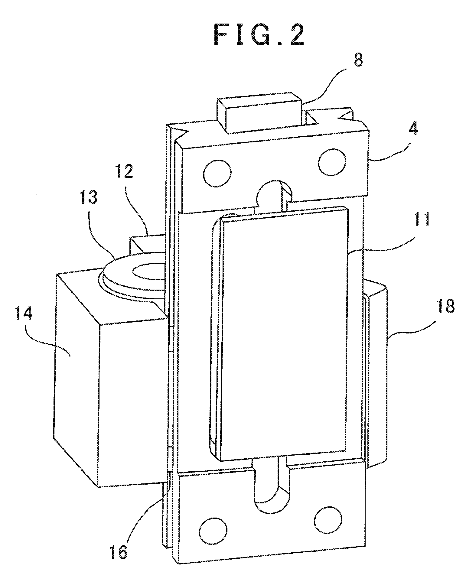
[0029]The guide unit 2 has a guide base 4 made of a flat plate in a rectangular shape, V-grooves 5a and 5b are formed on both the side end faces of the guide base 4 and a recessed portion 6 extending parallel to the V-grooves 5a and 5b is formed at a middle of an upper surface of the guide base 4.

[0030]A linear position detector 9 as consisted of a linear scale 7 and a linear sensor 8 is provided in the recessed portion 6. Further, an arithmetic unit 11 for calculating a position based on a signal from the linear sensor 8 is provided on a bottom surface of the guide base 4.

[0031]The slider unit 3 is provided so as to be movable along the V-grooves 5a a...


PUM

PropertyMeasurementUnit
Forceaaaaaaaaaa
Angleaaaaaaaaaa

Abstract

There is provided a slide guide unit comprising; a guide base having V-grooves formed on both the side end faces in parallel, a slide block having a facing surface facing one of the V-grooves on both the side ends, conical recesses formed at two positions on the facing surface facing the one V-groove with a predetermined interval, first steel balls fitted in the conical recesses and fitted in the one V-groove, a steel ball support plate with spring action as disposed on a side surface of the slide block on the other V-groove side and a necessary number of second steel balls as fitted in a steel ball holding groove and the other V-groove, wherein the steel ball support plate has the steel ball holding groove facing the other V-groove, wherein the steel ball support plate presses the second steel balls to the other V-groove and the slide block is movable along the one V-groove side and the other V-groove side via the first steel balls and the second steel balls.

Description

BACKGROUND OF THE INVENTION[0001]The present invention relates to a slide guide unit for supporting a slider with high accuracy and a surveying instrument using the slide guide unit.[0002]In a precision machine which requires a highly accurate positioning, for instance, a surveying instrument, a high accuracy of several seconds is required for setting a tilt angle. For instance, in a laser surveying instrument which projects a laser beam for measurement and performs an angle measurement and a distance measurement, a tilt of a laser luminescence device which projects a laser beam needs to be set in a unit of several seconds.[0003]As a mechanism for setting the tilt of the laser luminescence device, there is a mechanism which tilts the laser luminescence device by giving a linear displacement to an arm extending from the laser luminescence device and converts the linear displacement into a tilt angle of the laser luminescence device.[0004]In the tilt setting mechanism as described abo...

Claims


Application Information

Patent Timeline
IPC IPC(8): F16C29/00G01C15/00F16C29/04G01C15/14
CPCF16C29/004G01C15/14F16C29/04F16C29/005G01C15/004G01C15/00F16C2322/39F16C29/045F16C29/123F16C2370/20F16C2233/00
Inventor FUJIOKA, TAKAYUKI
Owner KK TOPCON
Why Eureka
Try Eureka