Angled facet broad-ridge quantum cascade laser

Active Publication Date: 2016-11-03
THE BOEING CO
View PDF2 Cites 1 Cited by
  • Summary
  • Abstract
  • Description
  • Claims
  • Application Information

AI Technical Summary

Benefits of technology

[0007]One particular advantage provided by at least one of the disclosed embodiments is that output light emitted from an angled facet (AF) quantum cascade laser (QCL) may form a nearly diffraction-limited, single-lobe in the lateral farfield axis centered on the direction perpendicular to the angled facet. A farfield lateral axis power efficiency corresponding to the single lobe may be greater than a power efficiency corresponding to a particular lobe of a dual-lobed output of a broad-ridge QCL that includes two flat facets (e.g., a flat facet FF-QCL). Further, the farfield lateral axis power effic

Problems solved by technology

One way to increase power from a QCL device is to broaden the ridge and contact, leading to mode competition between higher-order lateral modes and degraded lateral farfields.
Infrared countermeasure (IRCM) systems may be limited by the size and weight of their source transmitting components (e.g., light sources).
Light sources used by some I

Method used


Image

  • Angled facet broad-ridge quantum cascade laser
  • Angled facet broad-ridge quantum cascade laser
  • Angled facet broad-ridge quantum cascade laser

Examples


Embodiment Construction

[0017]Particular embodiments of the present disclosure are described below with reference to the drawings. In the description, common features are designated by common reference numbers throughout the drawings.

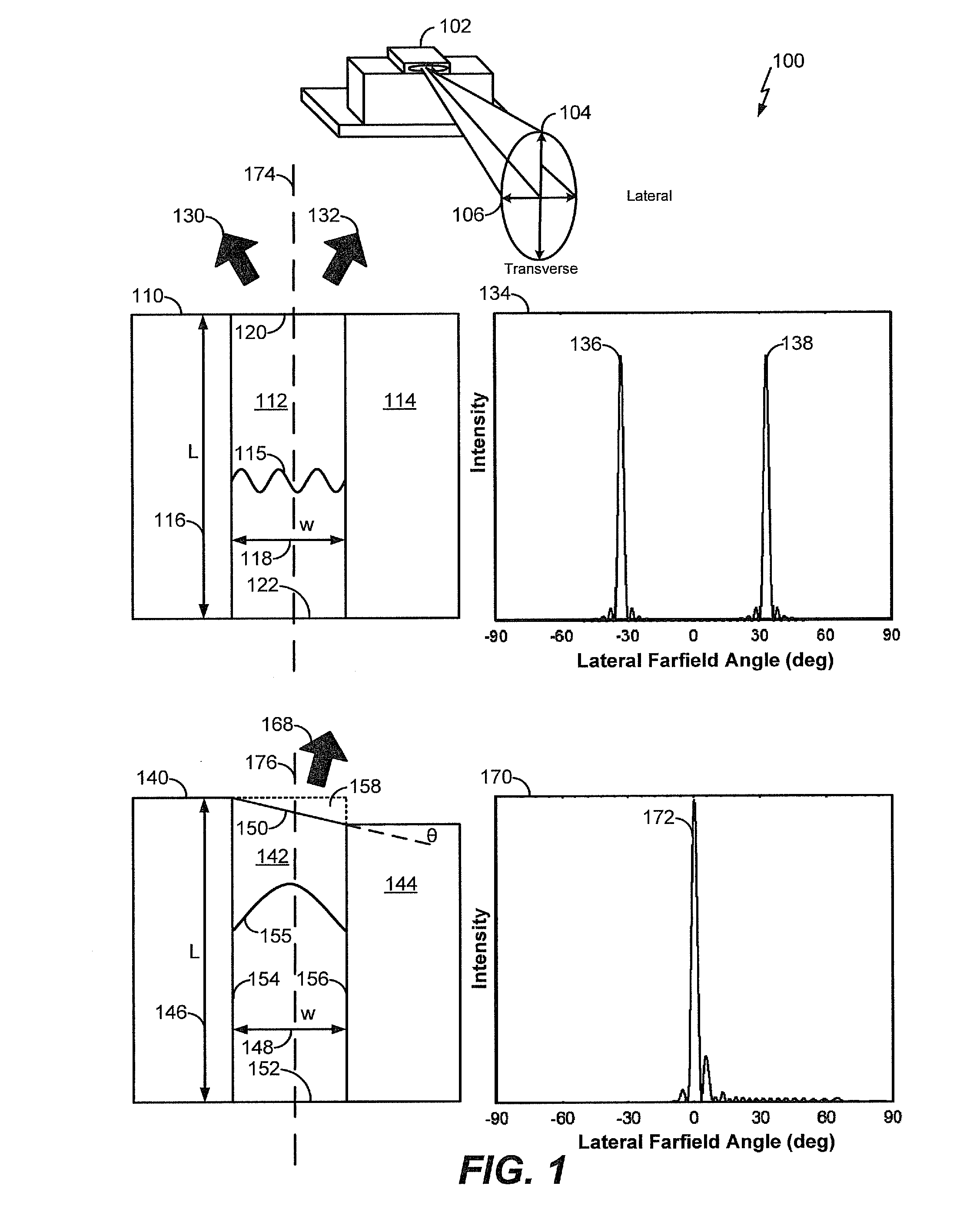
[0018]Referring to FIG. 1, an illustrative diagram 100 including a quantum cascade laser (QCL) 102 and a comparison between a flat facet QCL (FF-QCL) 110 and an angled facet QCL (AF-QCL) 140 is shown. In FIG. 1, a first diagram 134 illustrates simulated output intensity of first and second output light lobes 136, 138 (e.g., peaks) of the FF-QCL 110 at particular farfield angles. In FIG. 1, a second diagram 170 illustrates simulated output intensity of an output light lobe 172 (e.g., peak) of the AF-QCL 140 at particular farfield angles.

[0019]The QCL 102 is shown in a perspective view to illustrate reference directions described with respect to the FF-QCL 110, the AF-QCL 140, and the diagrams 134 and 170. The QCL 102 may correspond to the FF-QCL 110 or to the AF-QCL 140. Output...


PUM


Abstract

A particular quantum cascade laser includes a ridge-guide. The ridge-guide includes an angled facet that extends across a width of the ridge-guide and a flat facet that extends across the width of the ridge-guide. A first distance between the flat facet and the angled facet along a first side of the ridge-guide is different than a second distance between the flat facet and the angled facet along a second side of the ridge-guide.

Description

I. FIELD OF THE DISCLOSURE[0001]The present disclosure is generally related to an angled facet broad-ridge Quantum Cascade Laser.II. BACKGROUND[0002]Quantum Cascade Lasers (QCLs) are capable of producing room temperature outputs at wavelengths not easily accessible by other laser sources. Narrow-ridge QCL devices, with ridge widths of less than ten microns, have demonstrated lateral mode control while being limited in output power; they are therefore well-suited for lower power applications. One way to increase power from a QCL device is to broaden the ridge and contact, leading to mode competition between higher-order lateral modes and degraded lateral farfields. As the ridge and injection contact widths are increased, the laser begins to operate in a mixture of higher-order lateral modes across the ridge width. Additionally, the lasing lateral farfield forms a dual-lobed pattern that remains relatively stable with nearly fixed angular separation for the lobes. Further, for devices...

Claims


Application Information

Patent Timeline
IPC IPC(8): H01S5/10G01S7/495H01S5/042B64D45/00H01S5/22H01S5/34
CPCH01S5/3401H01S5/2018H01S5/22H01S5/028H01S5/0287H01S5/0624H01S5/1039H01S5/1085H01S5/2036H01S2301/166
Inventor TILTON, MICHAEL LEEDENTE, GREGORY C.
Owner THE BOEING CO
Why Eureka
Try Eureka