
Printed board for mounting microcomputer thereon, and control apparatus using same

a printed board and microcomputer technology, applied in the direction of printed circuit board receptacles, support structures, etc., can solve the problems of affecting the manufacturing of printed boards and thus control apparatuses, difficult to obtain the microcomputer being used, and difficult to replace. , to achieve the effect of eliminating the needless vast amount of time, labor and cost, and preventing a short supply situation

Inactive Publication Date: 2016-11-03
AUTONETWORKS TECH LTD +2
View PDF9 Cites 0 Cited by
  • Summary
  • Abstract
  • Description
  • Claims
  • Application Information

AI Technical Summary

Benefits of technology

This patent describes a printed board with at least two microcomputer mounting patterns, which allows for the use of different types of microcomputers on the same board. This eliminates the need for redesigning and manufacturing a new printed board when one type of microcomputer is in short supply. The printing board can be used for a longer period of time, while also making it easier to replace the microcomputer. This prevents shortages and saves time, money, and resources. The printed board can also be used in a control apparatus, making it easier to replace the microcomputer in case of an unexpected disaster.

Problems solved by technology

However, although there have not particularly been any problems in performing control of various types of electrical components of an automobile with use of a control apparatus constituted using a printed board optimized for each microcomputer that is to be mounted thereon as described above, in an unexpected case such as a disaster like the Great East Japan earthquake, obtaining the microcomputer being used becomes difficult for an extended period of time, and this has caused the problem of hindering the manufacturing of printed boards and thus control apparatuses.
In order to address this problem, it is conceivable to substitute a different microcomputer that has the same pin arrangement and size, for example, but it is easily anticipated that it will be difficult to obtain this microcomputer as well due to an increase in demand, and this cannot be said to be a preferable solution.
It is also conceivable to substitute a different microcomputer that has a different pin arrangement or size, but this requires the redesign and manufacture of a new printed board, which incurs a vast amount of time, labor, and cost, and therefore this cannot be said to be a preferable solution either.

Method used


Image

  • Printed board for mounting microcomputer thereon, and control apparatus using same
  • Printed board for mounting microcomputer thereon, and control apparatus using same
  • Printed board for mounting microcomputer thereon, and control apparatus using same

Examples


first embodiment

[0029]Next, a method of using the microcomputer mounting printed board 18 serving as the present invention will be described in detail using FIG. 4. As shown in FIG. 4, the microcomputer mounting printed board 18 is constituted including an insulated substrate 58 that is shaped as an approximately rectangular flat plate and is formed by a known insulating material such as glass epoxy resin, and a first microcomputer mounting pattern 64a and a second microcomputer mounting pattern 64b respectively provided on an upper surface 60 and a lower surface 62 of the insulated substrate 58. Specifically, a first microcomputer 32a and a second microcomputer 32b that have different pin arrangements can be mounted on the upper surface 60 and the lower surface 62 of the microcomputer mounting printed board 18, and therefore mounting patterns 64a and 64b optimized so as to accommodate each of the pin arrangements are provided. Accordingly, as shown in FIG. 4(a), the first microcomputer 32a as well...

second embodiment

[0032]Next, a microcomputer mounting printed board 66 serving as the present invention will be described in detail using FIG. 5, and members and portions having a structure similar to that in the above embodiment will be denoted in the figures by the same reference signs as in the above embodiment, and thus detail descriptions will not be given for them. Specifically, this microcomputer mounting printed board 66 is an embodiment different from the above embodiment in that a second microcomputer mounting pattern 68b is constituted including conduction paths 78b for connecting a mounting region 70b and pad portions 72b for the second microcomputer 32b to a wiring pattern 76a of a first microcomputer mounting pattern 68a.

[0033]As shown in FIG. 5(a), the first microcomputer mounting pattern 68a provided on the upper surface 60 of the microcomputer mounting printed board 66 is constituted including a mounting region 70a for the first microcomputer 32a, pad portions 72a, conduction paths...


PUM


Abstract

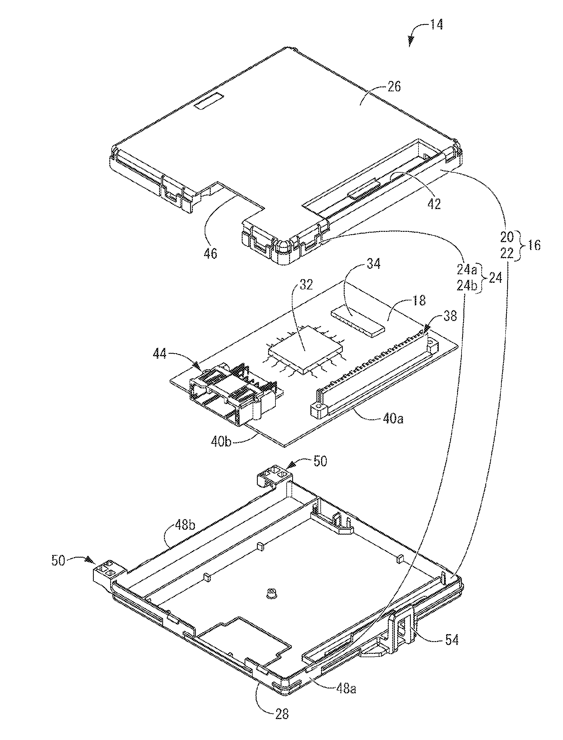
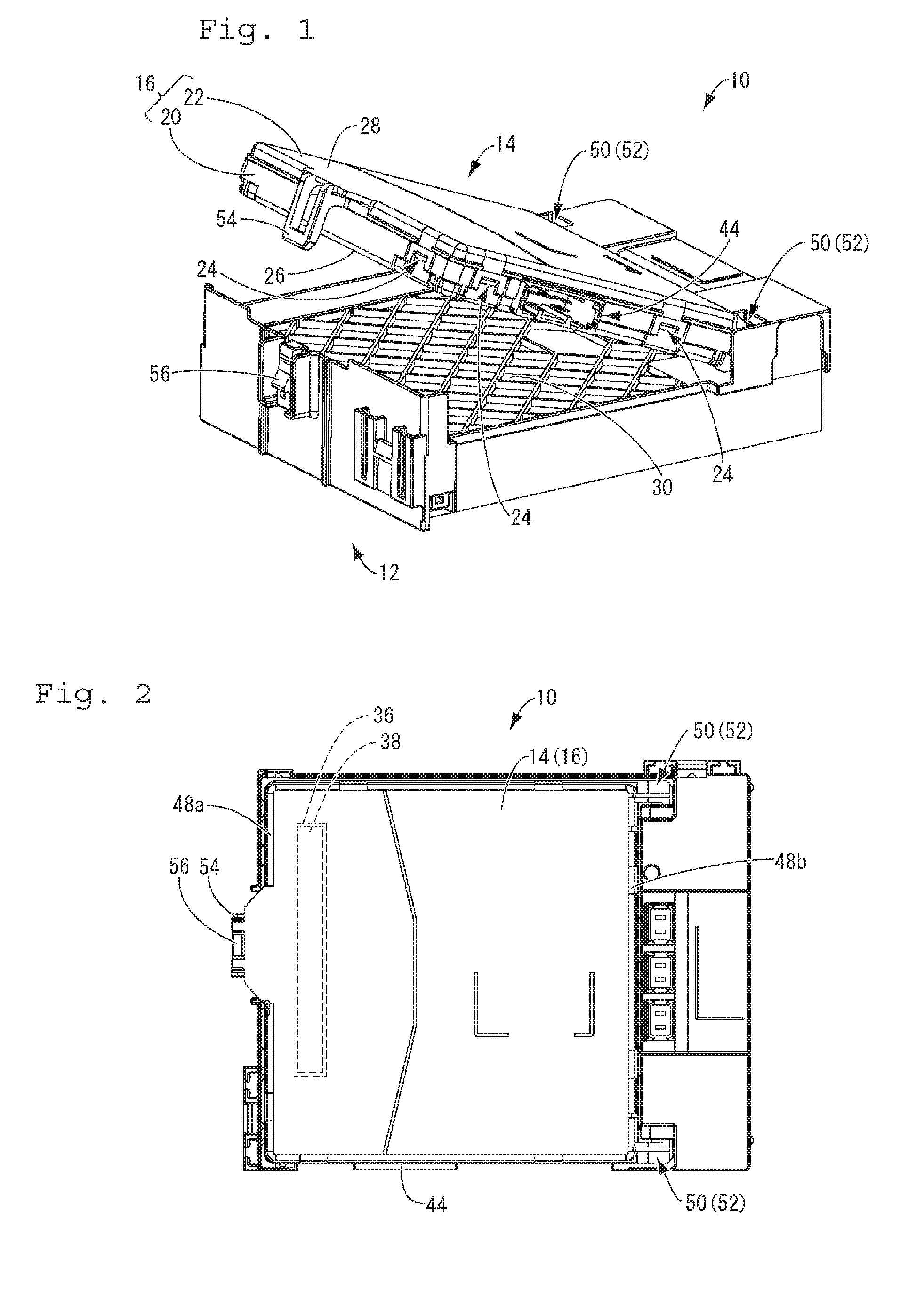
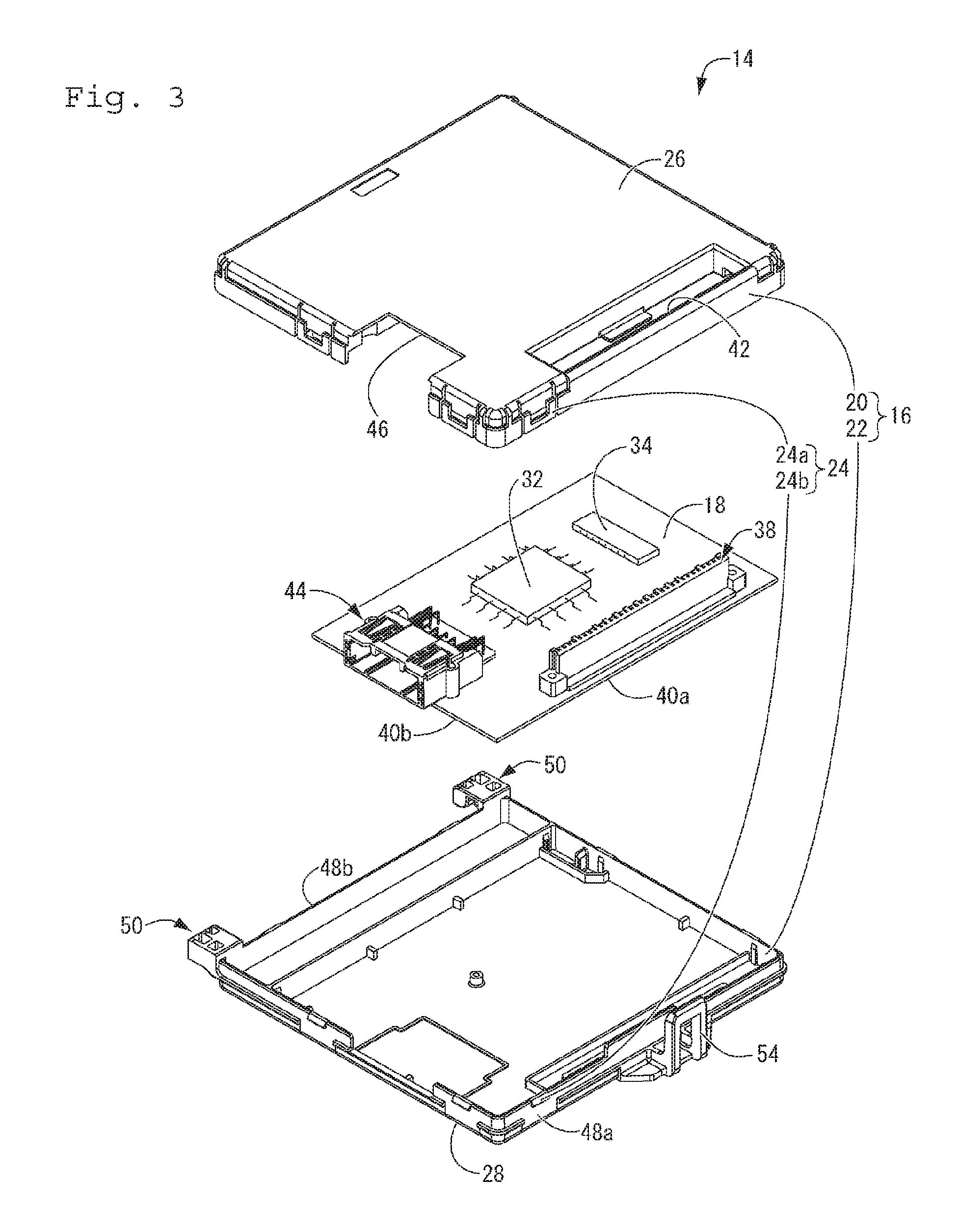
This invention provides a microcomputer mounting printed board that has a novel structure and enables the mounting of microcomputers having different pin arrangements or sizes without designing and manufacturing a new printed board, and a control apparatus that uses this microcomputer mounting printed board. At least a first microcomputer mounting pattern and a second microcomputer mounting pattern are formed on a microcomputer mounting printed board on which a microcomputer is to be mounted. Also, in a control apparatus in which an internal circuit is housed inside a case, the internal circuit is constituted including this microcomputer mounting printed board.

Description

CROSS-REFERENCE TO RELATED APPLICATIONS[0001]This application is the U.S. national stage of PCT / JP2014 / 081023 filed Nov. 25, 2014, which claims priority of Japanese Patent Application No. JP2013-258804 filed Dec. 16, 2013.FIELD OF THE INVENTION[0002]The present invention relates to a microcomputer mounting printed board on which different microcomputers can be mounted, and a control apparatus that uses this microcomputer mounting printed board.BACKGROUND[0003]Conventionally, microcomputers mounted on printed boards have been widely used for performing control of various types of electrical components in automobiles. More specifically, as shown in FIG. 1 of JP H11-39279A (Patent Document 1) for example, in addition to a microcomputer, various types of external components that are essential to operation of the microcomputer, such as a memory, are mounted on a printed board. For each microcomputer that is to be mounted on the printed board, a wiring pattern optimized so as to correspon...

Claims


Application Information

Patent Timeline
Patent Type & Authority Applications(United States)
IPC IPC(8): H05K1/18H05K7/14H05K1/11
CPCH05K1/181H05K2201/10545H05K7/1427H05K1/11H05K2203/175H05K1/0295
Inventor HAYASHI, TOMOYA
Owner AUTONETWORKS TECH LTD
Learn More