

Controller for vehicle
- Summary
- Abstract
- Description
- Claims
- Application Information
AI Technical Summary
Benefits of technology
Problems solved by technology
Method used
Image

Examples
first embodiment
[0033]the invention will be described below with reference to FIGS. 1 to 10. This embodiment provides a vehicle controller.
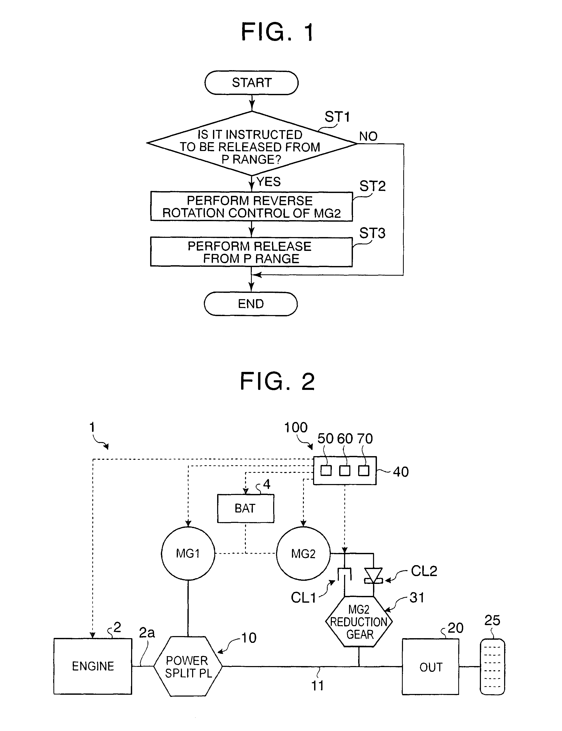
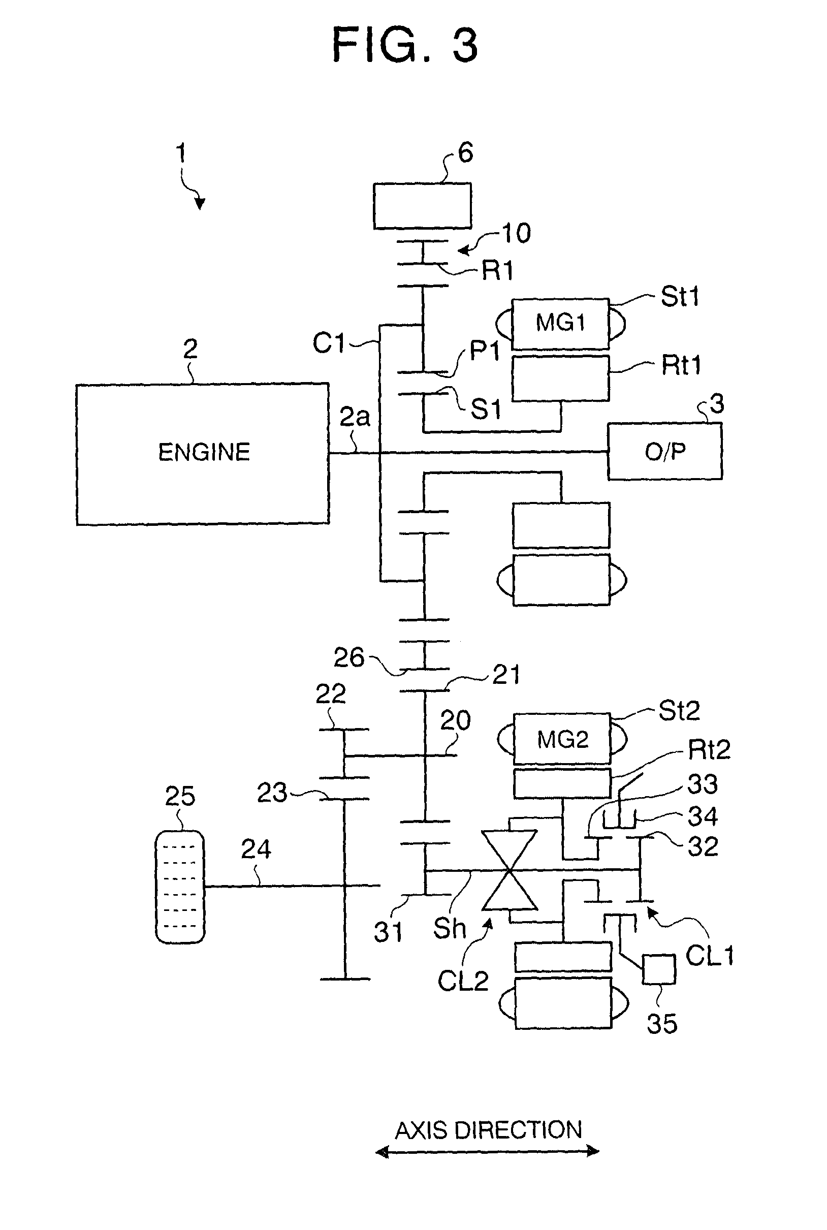
[0034]As illustrated in FIG. 2, a vehicle 1 according to this embodiment includes an engine 2, a first rotary machine MG1, a second rotary machine MG2, a battery 4, a planetary gear mechanism 10, a first clutch CL1, a second clutch CL2, a control unit 40, and an output shaft 20. The vehicle 1 is a hybrid vehicle including the engine 2 and two rotary machines MG1, MG2 as drive sources. The vehicle 1 may be a plug-in hybrid vehicle (PHV) that can be charged with an external power source.
[0035]A vehicle control system 100 according to this embodiment includes the engine 2, the second rotary machine MG2, the first clutch CL1, the second clutch CL2, and the control unit 40 in the vehicle 1.
[0036]The engine 2 converts the combustion energy of fuel into the rotation of an output shaft 2a and outputs the rotation. The planetary gear mechanism 10 has a function as a powe...
second embodiment
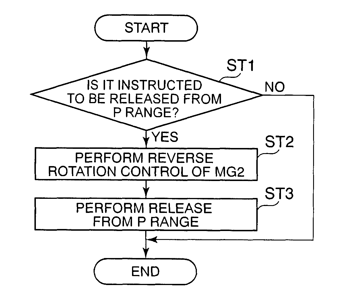
[0096]The operation of the vehicle control system 100 will be described below with reference to FIG. 12. The control flow illustrated in FIG. 12 is repeatedly performed with a predetermined cycle, for example, in travel. In step ST21, the reduction control instructing unit 50c determines whether the traveling on an uneven road is detected. The reduction control instructing unit 50c performs the determination of step S21, for example, on the basis of a variation in tire torque in travel. For example, the variation in tire torque can be calculated on the basis of the values of the engine torque and the MG2 torque Tm2 and the rotation speed of a tire. Instead, the traveling on an uneven road may be detected by the detection of slipping by a damper limiter unit disposed in the power transmission member 11 or the operation of an antilock brake system (ABS). The control flow goes to step ST22 when it is determined in step ST21 that the traveling on an uneven road is detected (Y in step S...
PUM
 Abstract
Description
Claims
Application Information