
Body coil assembly and method for generating radio-frequency field using the body coil assembly

Active Publication Date: 2011-02-03
SIEMENS HEALTHCARE GMBH
View PDF13 Cites 1 Cited by
  • Summary
  • Abstract
  • Description
  • Claims
  • Application Information

AI Technical Summary

Benefits of technology

[0007]In view of the above, an object of the present invention is to provide a body coil assembly that improves the signal-to-noise ratio received in the magnetic resonance system. The present invention also encompasses a method for generating a radio-frequency field by using the body coil assembly, so as to improve the signal-to-noise ratio received in the magnetic resonance system.
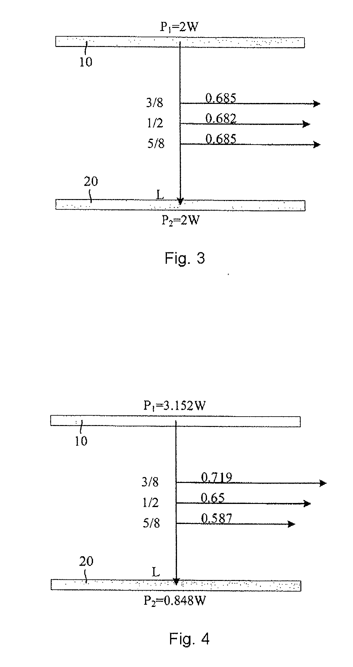
[0020]It can be seen from the abovementioned solutions that, since in the present invention the transmitting powers of the first coil and the second coil are controlled, so as to provide unequal transmitting powers to the first coil and the second coil when needed, a required radio-frequency field distribution is generated to form a stronger field strength at a certain position, thus improving the signal-to-noise ratio of that position during the receiving process. Furthermore, compared with the prior art in which equal powers are used for the first coil and the second coil, the technical solutions of the present invention are capable of reducing the total power transmitted, thereby saving power and reducing the energy consumption.

Problems solved by technology

In addition, in order to improve the signal-to-noise ratio of the received signals, a conventional magnetic resonance system generally uses measures for improving the scanning sequence, but such an approach is very complicated to implement and cannot save powers.

Method used


Image

  • Body coil assembly and method for generating radio-frequency field using the body coil assembly
  • Body coil assembly and method for generating radio-frequency field using the body coil assembly
  • Body coil assembly and method for generating radio-frequency field using the body coil assembly

Examples


Embodiment Construction

[0026]According to the antenna theory, the receiving and the transmitting are reciprocal, therefore the transmitting efficiency is equivalent to the sensitivity when receiving, and improving the sensitivity results in improvement to the signal-to-noise ratio.

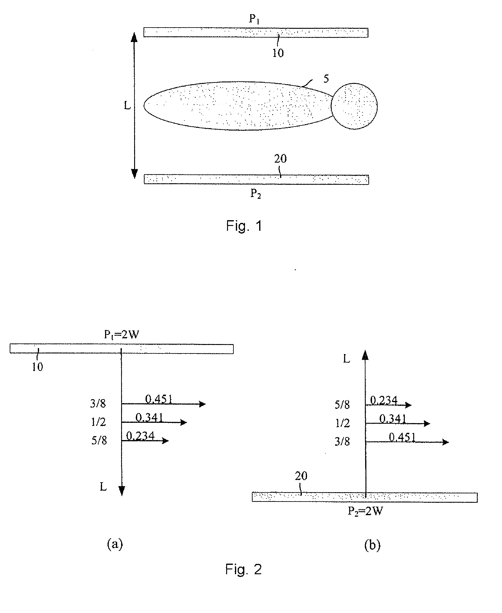
[0027]In FIG. 2, the field strengths of the first coil 10 and the second coil 20 at different positions in space are indicated schematically.

[0028]The equation for calculating the transmitting efficiency is:

k=BP

in which k is the transmission efficiency, B is the magnetic field strength, P is the transmitting power of the first coil or the second coil. It can be seen from the equation that, the transmission efficiency is proportional to the field strength.

[0029]As shown in FIG. 2a, the transmitting power of the first coil 10 is 2 W, then the field strength of the first coil 10 is 0.451 at a distance of 3 L / 8 from the first coil, 0.341 at an distance of L / 2 from the first coil, and 0.234 at a distance of 5 L / 8 from the first coil ...


PUM


Abstract

A body coil assembly for a magnetic resonance apparatus has a first coil and a second coil for generating a radio-frequency field in space, and a power control apparatus connected to the first coil and the second coil for controlling the transmitting power of the first coil and the second coil. In a method for generating a radio-frequency field using such a body coil assembly, the transmitting powers of the first coil and the second coil are controlled, to provide unequal transmitting powers to the first coil and the second coil when needed to generate a required radio-frequency field distribution, so as to form a stronger field strength at a certain position, thus improving the signal to noise ratio at that position during the receiving process.

Description

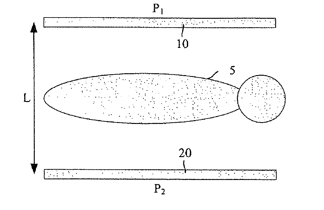
BACKGROUND OF THE INVENTION[0001]1. Field of the Invention[0002]The present invention relates to a body coil in the field of magnetic resonance (MR) and, particularly, to a body coil assembly and a method for generating a radio-frequency field by using the body coil assembly.[0003]2. Description of the Prior Art[0004]In magnetic resonance systems employing a vertical magnet (in which the direction of main magnetic field is perpendicular to Z axis), the body coils are divided into two parts disposed oppositely, i.e., they include a first coil 10 and a second coil 20 as shown in FIG. 1, and the distance between the first coil 10 and the second coil 20 is L. If the first coil 10 and the second coil 20, as shown in FIG. 1, are disposed oppositely one above the other, and a patient 5 lies horizontally therebetween, then the first coil 10 and the second coil 20 are referred to respectively as an upper coil and a lower coil. The first coil 10 and the second coil 20 can be arranged differen...

Claims


Application Information

Patent Timeline
IPC IPC(8): G01R33/44
CPCG01R33/34046G01R33/5612G01R33/3607G01R33/34061
Inventor WANG, JIAN MINWANG, LANXING, YAOXUE, MIN
Owner SIEMENS HEALTHCARE GMBH
Learn More