
Standup paddle outrigger watercraft

a technology of stand-up paddleboards and watercraft, which is applied in the field of personal watercraft, can solve the problems of sacrificing the stability of sup boards designed for speed, the wide, flat shape of surfboard hulls, and the limited maneuverability of typical sup boards, so as to improve efficiency, speed, stability and maneuverability.

Inactive Publication Date: 2016-11-10
DION DANIEL JOSEPH
View PDF3 Cites 0 Cited by
  • Summary
  • Abstract
  • Description
  • Claims
  • Application Information

AI Technical Summary

Benefits of technology

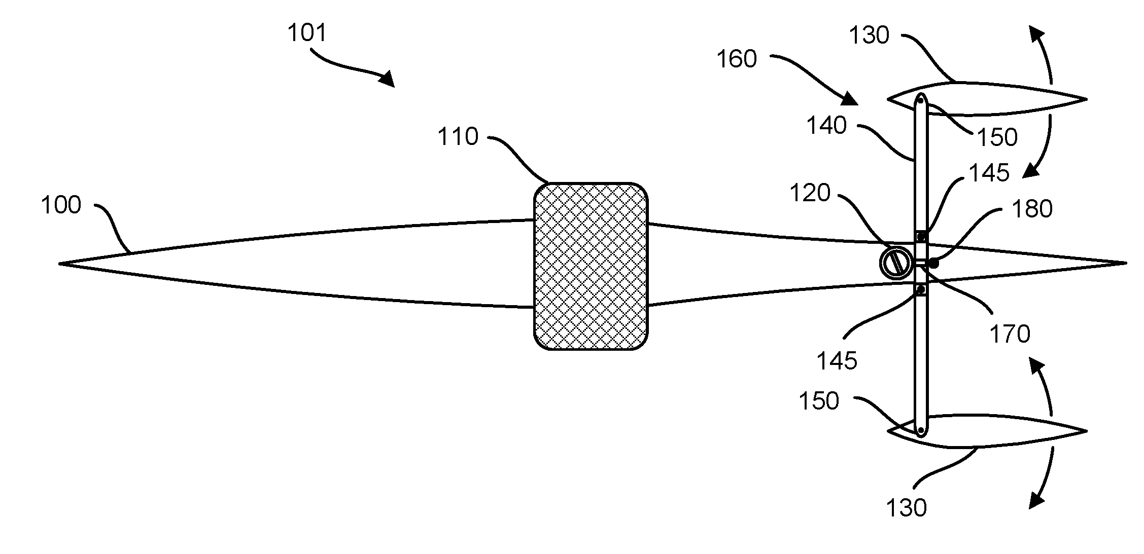
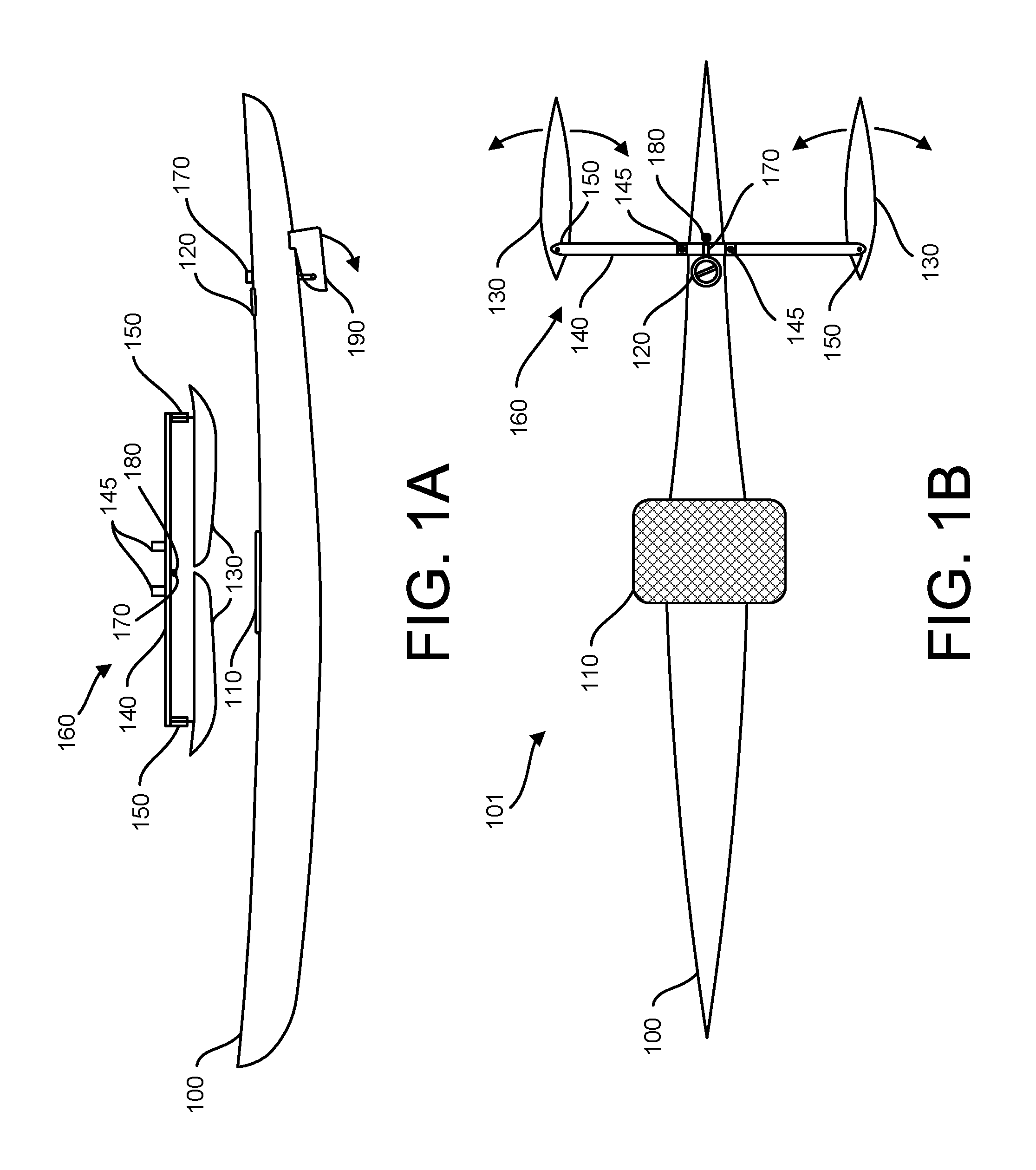
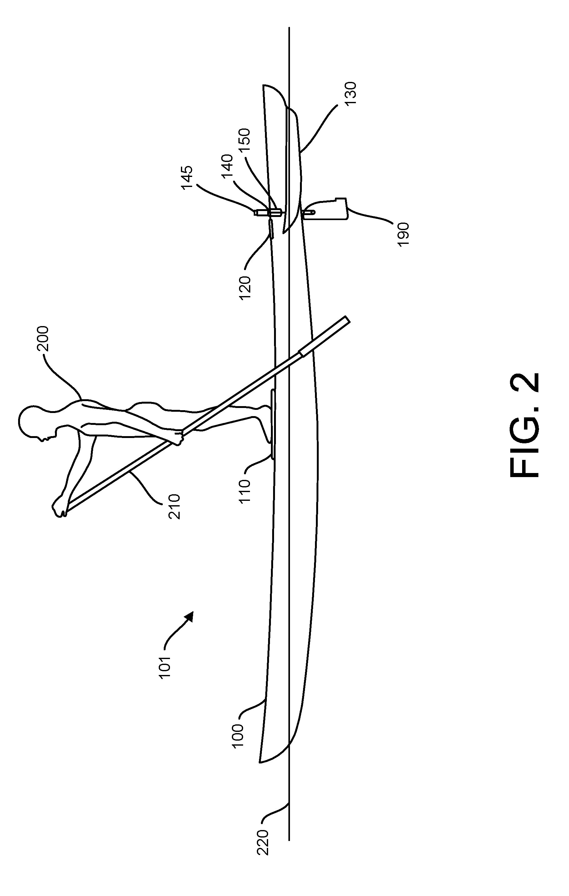
The patent describes a new type of standup paddleboard outrigger called the SUPO personal watercraft. This new design improves efficiency, speed, stability, and maneuverability over existing standup paddleboards. It has a narrow hull that provides optimal hydrodynamic efficiency for paddling in flat water. It also has two outrigger pontoons on each side, which provide lateral stability. The paddler shifts body weight through the feet to achieve maneuverability, so there is no need to switch the paddle from side to side to maintain a straight course. The SUPO design combines the speed and maneuverability of a solo single person outrigger craft with the advantages of a SUP, such as using a longer paddle to achieve greater leverage. It is highly stable, maneuverable, and fast self-propelled personal watercraft. The pontoon bridge has a central pivot point so that the pontoons can swing forward and adjacent to the hull for easy storage and transport. The outriggers not only provide lateral stability / support, they also rotate while maintaining a parallel relationship to each other, in order to make turns. Maneuvering the craft is solely accomplished by shifting body weight, using a paddle for turning is not necessary.

Problems solved by technology

The wide, flat shape of a surfboard hull is limited in terms of hydrodynamic efficiency for paddling; it is based on a planing hull designed to skim across the surface of water at high speed.
SUP boards designed for speed sacrifice stability because they are narrow which makes them tippy.
Maneuverability of a typical SUP board is limited as well; it is achieved by the use of the paddle and dependent on the skill level of the paddler.

Method used


Image

  • Standup paddle outrigger watercraft
  • Standup paddle outrigger watercraft
  • Standup paddle outrigger watercraft

Examples


Embodiment Construction

[0047]This document describes a standup paddleboard outrigger watercraft, which enables a considerable improvement in efficiency, speed, stability and maneuverability over existing standup paddle watercraft.

[0048]In the following description, numerous specific details are set forth. However, it is understood that embodiments may be practiced without these specific details. In other instances, well-known materials, structures, and techniques have not been shown in detail in order not to obscure the understanding of this description.

[0049]FIG. 1A illustrates a side view of a SUPO assembly 101 in a disassembled, storage position. The SUPO includes a hull 100 and an outrigger bridge assembly 160. The hull 100 is designed as a displacement hull: long, narrow, sleek and hollow in order to make it as lightweight as possible. In some preferred implementations, the hull 100 is made of carbon fiber, but in other implementations may include any combination of glass-reinforced plastic, polyeste...


PUM


Abstract

A standup paddleboard outrigger includes a long, narrow, lightweight displacement hull and a pair of outrigger pontoons mounted to a bridge. The two parts disengage for easy storage and transport. The hull has a platform to stand on. Paddling with a long handled paddle propels the craft through the water. The outriggers provide lateral stability / support and actuate the rudder in order to make turns. When a person stands on the platform and shifts body weight, the rudder will rotate to the right and the craft will turn to the right. The more weight that is shifted, the greater the turning action. The responsiveness to the shift of body weight can be adjustable for personal preference either firmer or more flexible, as is the turning response of the rudder fine or coarse turning.

Description

CROSS REFERENCE TO RELATED APPLICATIONS[0001]This application claims the benefit of U.S. patent application Ser. No. 62 / 179,383, filed on May 6, 2015 and U.S. patent application Ser. No. 62 / 388,276, filed on Jan. 26, 2016, which are incorporated by reference herein in their entirety.TECHNICAL FIELD OF THE INVENTION[0002]The present disclosure relates to personal watercraft, and more particularly to a standup paddleboard outrigger watercraft.BACKGROUND OF THE INVENTION[0003]For thousands of years, river, lake and coastal cultures have stood within their canoes and upon rafts to paddle in a standing position. Conceptually therefore, the idea of standing and paddling using an extended paddle is far from being a new concept. Recently, with modernized materials and designs, standup paddle boarding SUP has become significantly more popular both as casual recreation and as a competitive sport. Although SUPs have evolved over time, current designs are based on the rudimentary concept of an ...

Claims


Application Information

Patent Timeline
Patent Type & Authority Applications(United States)
IPC IPC(8): B63B35/79B63H25/38
CPCB63H25/38B63B35/7916B63B1/14B63B32/10B63B32/70B63B43/14B63B32/53
Inventor DION, DANIEL JOSEPH
Owner DION DANIEL JOSEPH
Learn More