

Method and apparatus for aircraft inspection
- Summary
- Abstract
- Description
- Claims
- Application Information
AI Technical Summary
Benefits of technology
Problems solved by technology
Method used
Image

Examples
second embodiment
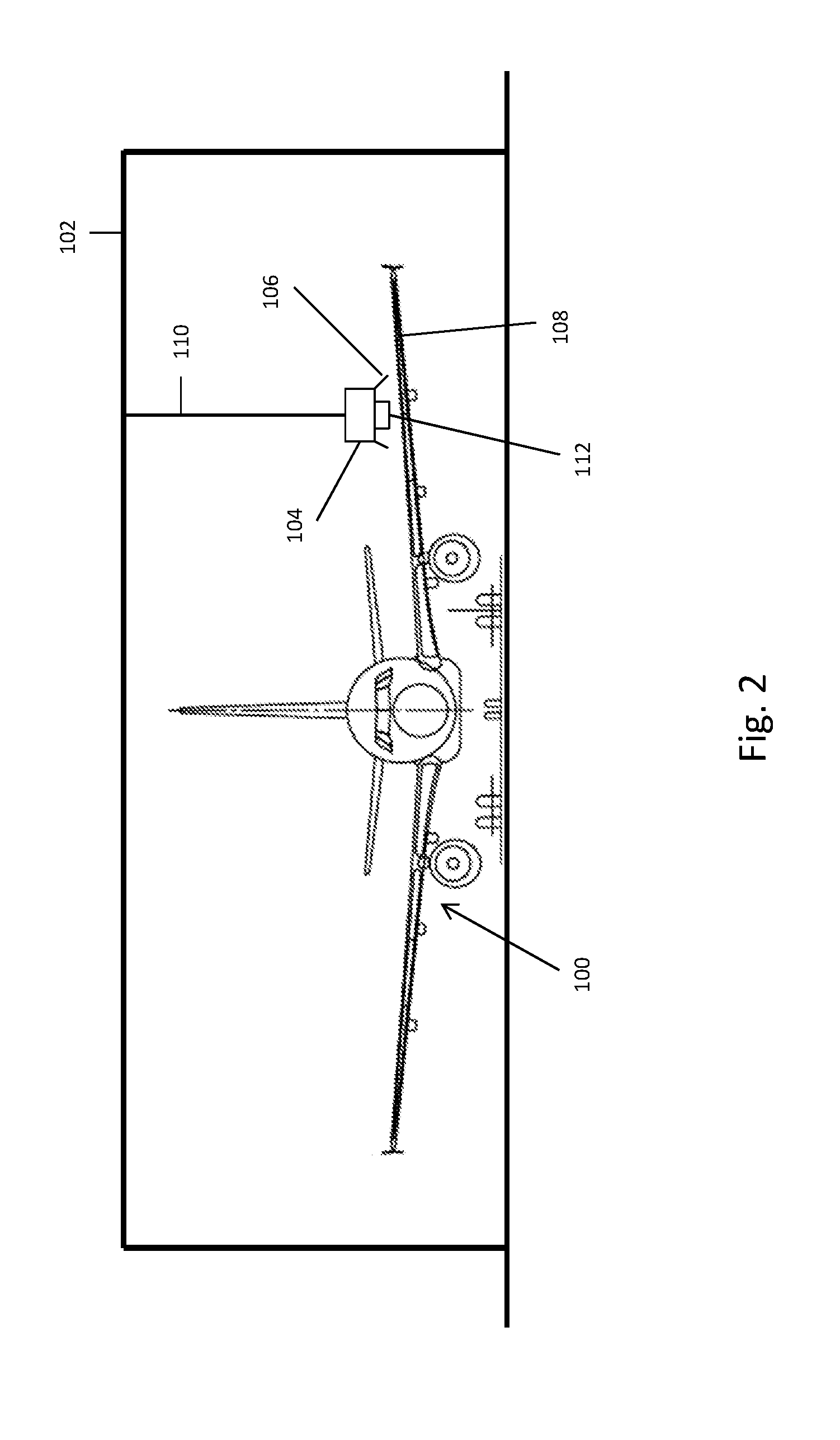
[0038]FIG. 2 shows the invention. An aircraft 100 may be stationary within a frame 102. The frame 102 may be within an aircraft hanger. A robotic device 104 is provided including a plurality of legs 106 which enable the robotic device to move along a wing 108 of the aircraft 100. The robotic device 104 may be attached to an umbilical cord 110, which may lift the robotic device 104 away from the wing 108 or place the robotic device 104 on the wing 108, and also provides power to the robotic device 104 via a charging lead. The robotic device 104 includes a sensor 112, in this case an ultrasound sensor. The robotic device 106 may inspect the aircraft wing 108 for structural defects as follows.
[0039]The aircraft may be located underneath the frame 102. The umbilical device 110 may position the robotic device 104 onto the aircraft wing 108 and then release the robotic device 104 for free movement around the wing 108. Once the robotic device is free to move, it starts to move around the w...
first embodiment
[0040]The robotic device 104 may store and / or transmit data concerning the inspection process as described for the invention.
[0041]Unlike the first embodiment of the invention, the robotic device may be used to inspect a plurality of different aircraft. The apparatus according to the second embodiment of the invention may allow a single inspection station to be used to inspect a large number of aircraft. The details of the aircraft inspected and the results of the inspections may be stored at a central storage facility.
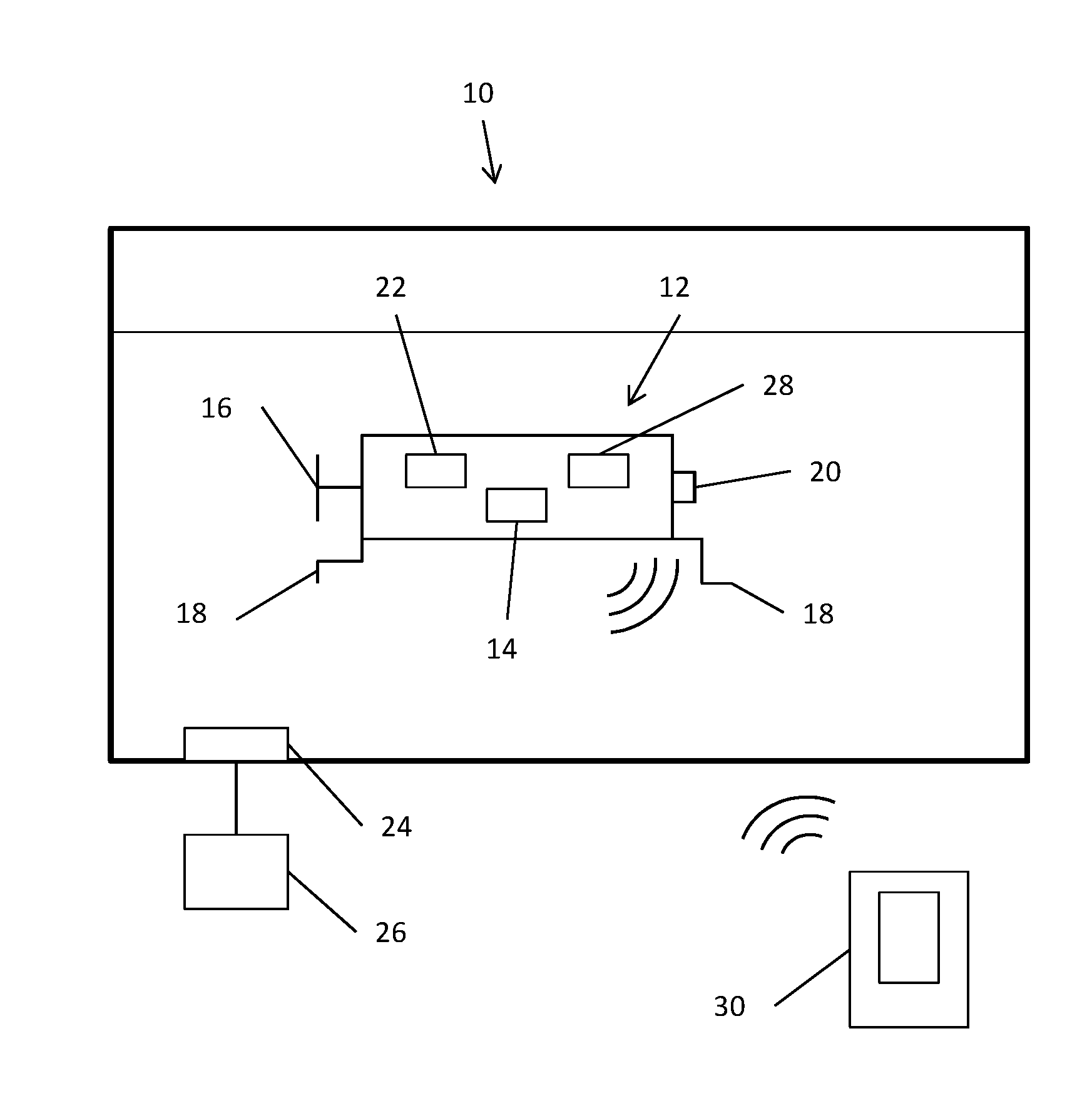
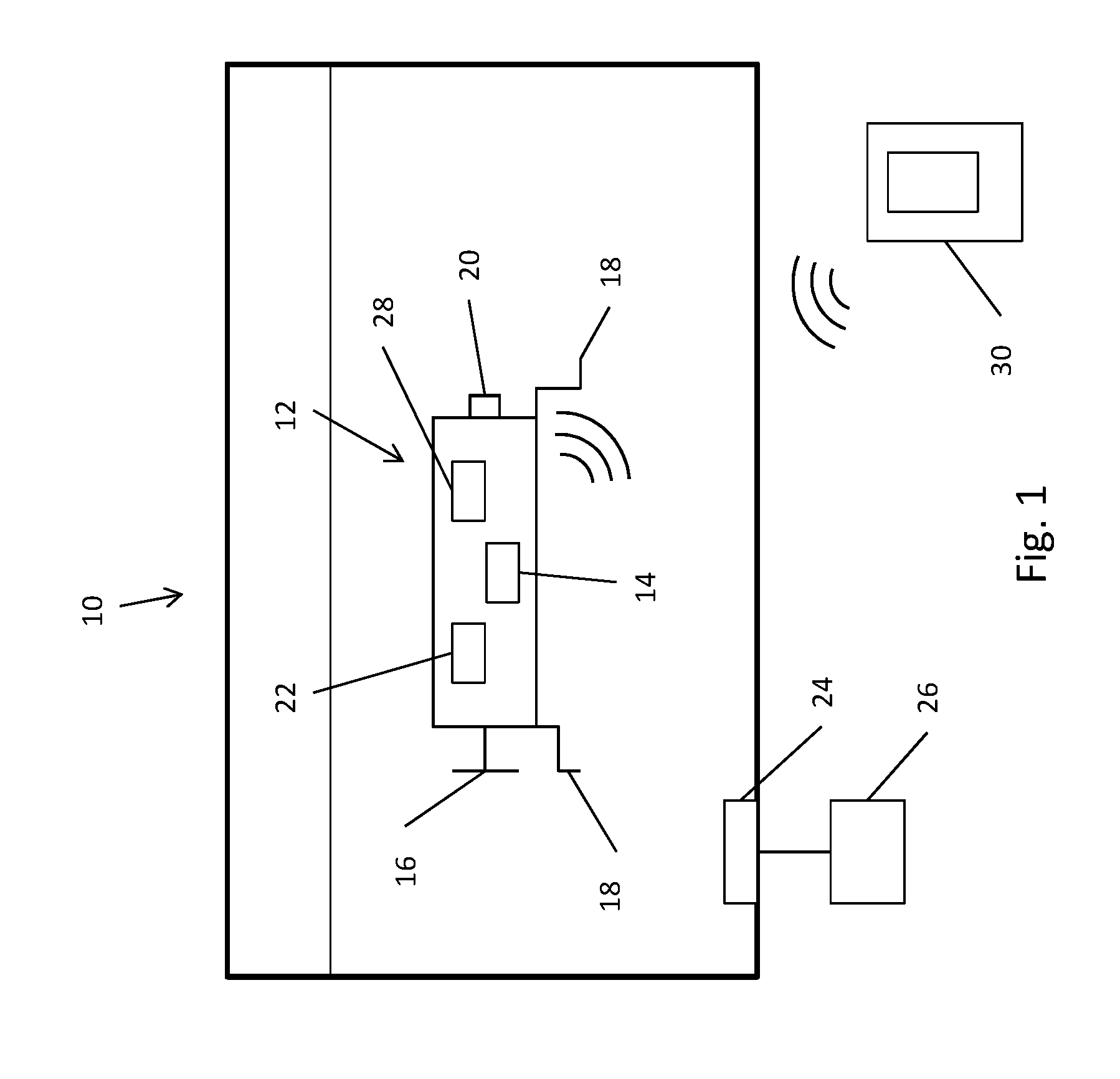
[0042]The aircraft 100 may also include a fuel tank 10 as described with regards to FIG. 1 of the application.
[0043]Whilst the second embodiment of the invention has been described in relation to the inspection of an aircraft wing, the robotic device 104 could be used to inspect other parts of an aircraft, for example the fuselage, for structural defects. In alternative embodiments, the robotic device 104 could be used to inspect internal parts of the aircraft, for ex...
PUM
 Abstract
Description
Claims
Application Information