Method and system for vacuum generation using a throttle comprising a hollow passage

a technology of vacuum generation and hollow passages, which is applied in the direction of machine/engine, combustion-air/fuel-air treatment, charge feed systems, etc., can solve the problems of limited vacuum generation potential of the throttle, increased related expenses, and additional expenses, so as to achieve limited vacuum generation potential and increase related expenses

Active Publication Date: 2016-11-10
FORD GLOBAL TECH LLC
View PDF2 Cites 10 Cited by
  • Summary
  • Abstract
  • Description
  • Claims
  • Application Information

AI Technical Summary

Benefits of technology

[0003]In yet another example embodiment shown by Bergbauer et al. in U.S. Pat. No. 8,261,716, a control bore is located in the wall of the intake such that when the throttle plate is at idle position, vacuum generated at the periphery of the throttle is used for a vacuum consumption device. Therein, the positioning of the throttle plate in an idle position provides a constriction at the throttle plate's periphery. The increasing flow of intake air through the constriction results in a venturi effect that generates a partial vacuum. The control bore is sited so as to utilize the partial vacuum for a vacuum cons...

Problems solved by technology

However in the approaches described above, the vacuum generation potential of the throttle is limited.
However, fabricating these control bores may result in significant modifications to the design of the intake passage which can increase related expenses.
In the approaches that use one or more aspirators to generate vacuum, additional expenses may be incurred because of individual parts that form the aspirator including nozzles, mixing and diffusion sections, and check valves.
Further, at idle or low load conditions, it may be difficult to control the total air flow rate into the intake manifold since the flow rate is a combination of leakage flow from the throttle and airflow from the aspirator.
Ty...

Method used


Image

  • Method and system for vacuum generation using a throttle comprising a hollow passage
  • Method and system for vacuum generation using a throttle comprising a hollow passage
  • Method and system for vacuum generation using a throttle comprising a hollow passage

Examples


embodiment 300

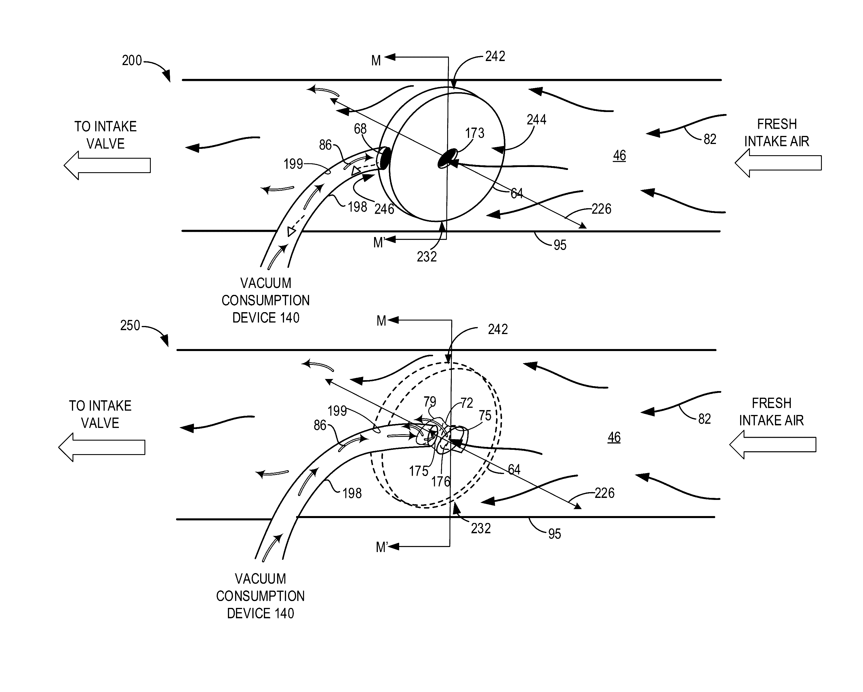
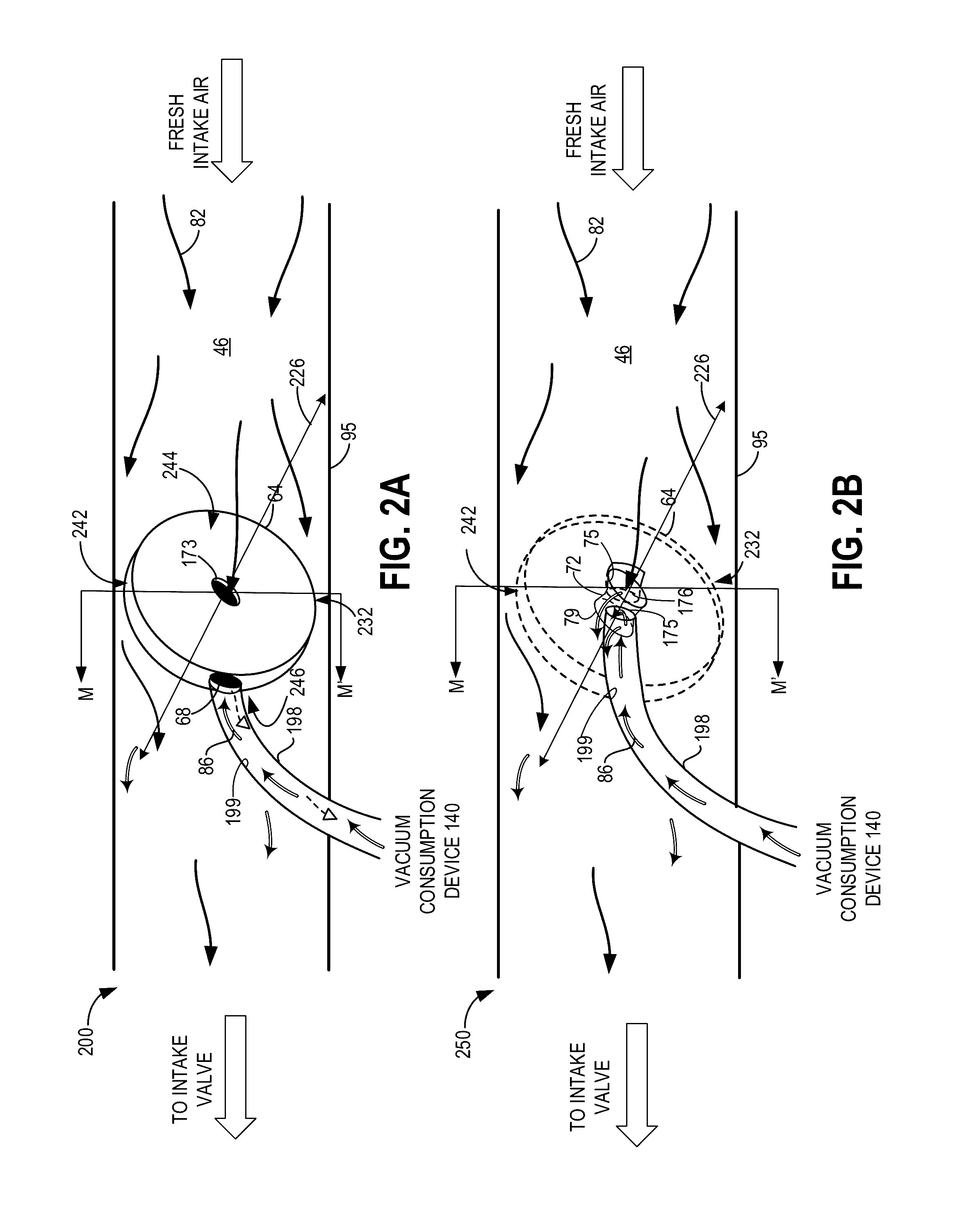
[0050]Turning now to FIG. 3, it shows an embodiment 300, where throttle plate 64 and its arrangement in the intake conduit 95 is shown in more detail. FIG. 3 is a cross sectional view of throttle plate 64 positioned within intake conduit 95, where the cross sectional plane is taken along line M-M′ of FIGS. 2A-2B. Note that components previously introduced in FIG. 1 and FIGS. 2A-2B are numbered similarly in FIG. 3, and may not be reintroduced.

[0051]Throttle plate 64 is positioned in the example of FIG. 3 in a closed first position. In the closed first position, the throttle plate 64, is approximately perpendicular to the walls of the intake conduit 95. As such, the flow of intake air 82 around the throttle plate 64 may be reduced. Said another way, the opening that exists between the edges of the throttle plate and the walls of the conduit 95 may decrease with increasing deflection of the throttle plate towards the closed first position. In some examples, intake air 82 may not flow a...

embodiment 400

[0061]FIG. 4A shows an embodiment 400, where throttle plate 64 is in the closed first position. Thus, throttle plate 64 may be approximately perpendicular to the walls of conduit 95. Throttle plate 64 may rotate about an axis of rotation R-R′ shown in FIG. 4A. Thus, in FIGS. 4B-4D, throttle plate 64 may be shown rotated about the axis of rotation R-R′ in different positions. A portion of conduit 198 exterior to conduit 95 is shown in dotted lines. However, as explained above with reference to FIG. 3, hollow shaft 74 may extend radially inward from a location on the circumference of throttle plate 64, to the interior passage 72. As shown in the examples of FIGS. 4A-4D, the hollow shaft 74 may extend radially between the interior passage 72, and an edge of the throttle plate 64, along the axis of rotation R-R.′ Thus, the walls of the hollow shaft 74 may be parallel to the axis of rotation R-R.′ As such, the hollow shaft 74 may not move, but may rotate as the throttle plate 64 rotates ...

embodiment 425

[0062]FIG. 4B shows an embodiment 425, where the throttle plate 64 is rotated along the axis of rotation R-R,′ relative to the closed first position shown in FIG. 4A to an intermediate second position. Specifically, throttle plate 64 is rotated in FIG. 4B so that the top edge 242, moves upstream in the conduit 95, and the bottom edge 232 moves downstream in conduit 95 relative to their positioning shown in the closed first position of FIG. 4A. Put more simply, in FIG. 4B, the throttle plate 64 is shown rotated clockwise from the closed first position. However, the conduit 198 and / or hollow shaft 74 may remain in the same position in FIG. 4B, as in FIG. 4A, since they may be centered on the axis of rotation R-R′ of the throttle plate 64.


PUM


Abstract

Various systems and methods are described for generating vacuum within an engine intake. A system may comprise an intake throttle including a throttle plate, where the throttle plate may comprise a hollow interior passage, which in turn may be coupled to a vacuum consumption device. When vacuum is demanded by the vacuum consumption device, the throttle plate may be adjusted to increase airflow through the interior passage and vacuum may be generated at a constricted portion of the interior passage by flowing intake air through the interior passage of the throttle plate.

Description

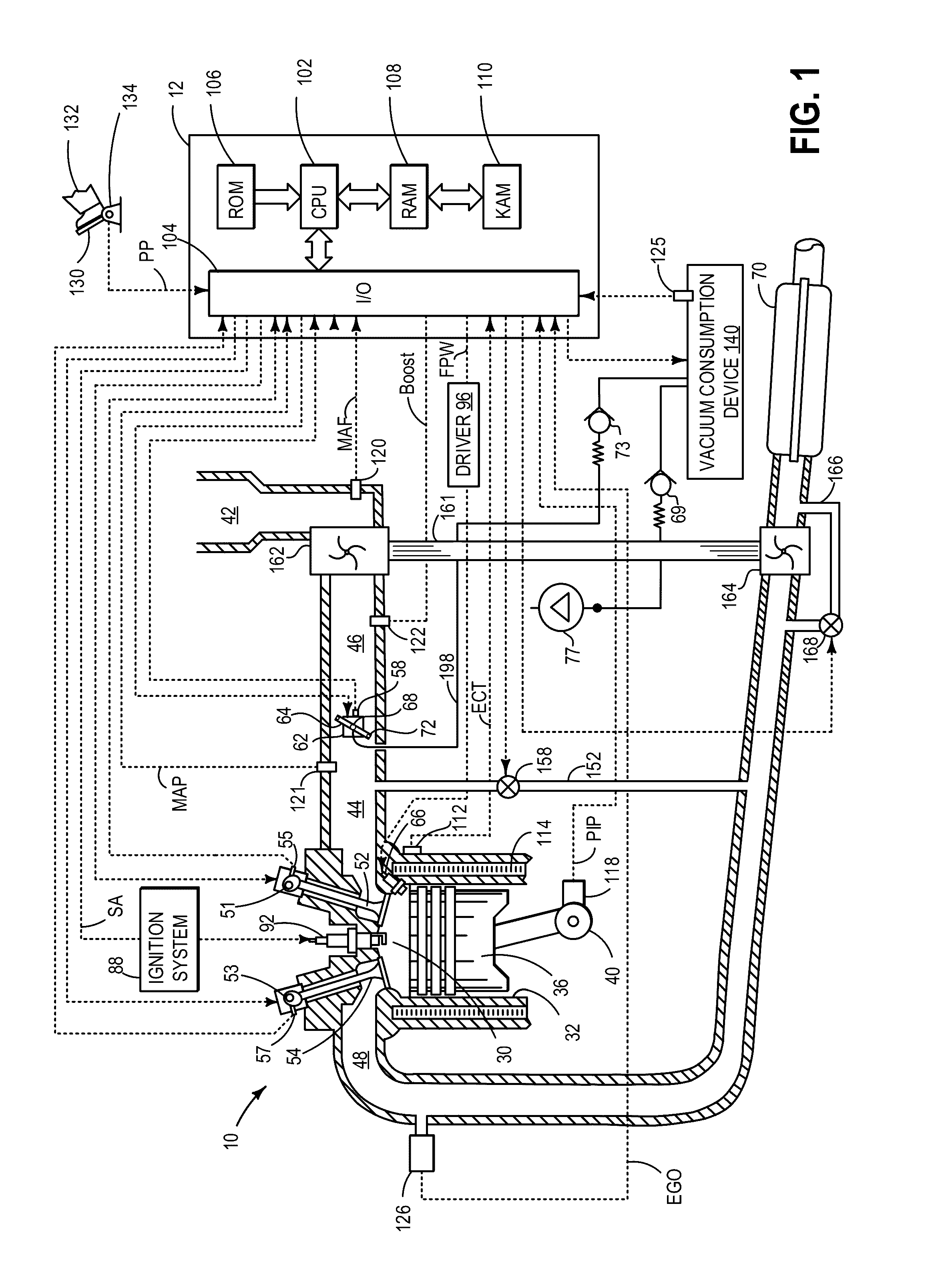
TECHNICAL FIELD[0001]The present application relates to vacuum generation in an intake via a throttle plate.BACKGROUND AND SUMMARY[0002]Vehicle systems may include various vacuum consumption devices that are actuated using vacuum. These may include, for example, a brake booster and a purge canister. Vacuum used by these devices may be provided by a dedicated vacuum pump. In other embodiments, one or more aspirators (alternatively referred to as ejectors, venturi pumps, jet pumps, and eductors) may be coupled in the engine system that may harness engine airflow and use it to generate vacuum.[0003]In yet another example embodiment shown by Bergbauer et al. in U.S. Pat. No. 8,261,716, a control bore is located in the wall of the intake such that when the throttle plate is at idle position, vacuum generated at the periphery of the throttle is used for a vacuum consumption device. Therein, the positioning of the throttle plate in an idle position provides a constriction at the throttle p...

Claims


Application Information

Patent Timeline
IPC IPC(8): F02M35/10
CPCF02M35/10229F02D9/1015F02D9/1035F02D9/1055F02D37/00F02D2009/024F02D9/1005F16K1/222F16K2200/401F02D9/02
Inventor ZHANG, XIAOGANG
Owner FORD GLOBAL TECH LLC
Why Eureka
Try Eureka