Axial flux brushless permanent magnet electrical machine rotor

a permanent magnet, brushless technology, applied in the direction of dynamo-electric machines, magnetic circuit rotating parts, magnetic circuit shapes/forms/construction, etc., can solve the problems of reducing the axial force of the rotor, the retaining device does not provide the primary structural restraint to carry the centrifugal load from the magnet to the rotor hub, etc., to achieve the effect of minimizing structural mass and maximizing rotor strength

Active Publication Date: 2016-11-10
LAUNCHPOINT ELECTRIC PROPULSION SYST INC
View PDF2 Cites 39 Cited by
  • Summary
  • Abstract
  • Description
  • Claims
  • Application Information

AI Technical Summary

Benefits of technology

[0021]It is an object of this invention to maximize rotor strength for high-speed operation while minimizing structural mass.

Problems solved by technology

It is also known that centrifugal stresses in the rotor may cause the magnets to crack because the magnet material is brittle and may not tolerate much tensile stress.
This technique is difficult to implement in practice as the carbon fiber wraps needs a significant preload / pre-stress tension to ensure that it carries the tensile load rather than the bonds of the magnets to the steel rotor.
By way of pins 37, apertures 39, and connecting clips 35, the retaining device assists in keeping the magnets attached to the rotor in the event of an adhesive failure, but the retaining device does not provide the primary structural restraint to carry the centrifugal loads from the magnets to the rotor hub.
Less expensive rectangular magnets may be used, but this results in a lower magnetic field and large wedge shaped gaps between the magnets at the periphery of the rotor.
The adhesive bond in such a design is subject to failure at high rotor speeds.
Depending on the detailed shape of the rotor, the centrifugal force may cause expansion, convex cupping, concave cupping and other distortion of the annular rotor.
Further, any deformation of the rotor may apply stresses to the magnets which generally have modest strength and are brittle.
Thus, at any reasonable speed for a machine categorized as “high speed” with magnets in a solid annular ring and a lightweight rotor, any bonds between the magnets will break and even the magnets themselves are subject to breaking.
Because the magnets may not withstand the centrifugal tensile forces from high speed operation, those forces must instead be taken by the rotor structure such as the backing plate that the magnets are bonded to.
However, if the rotor structure is thin and lightweight, then the rotor materials must undergo a significant strain as they will be under significant centripetal tensile stress.
The magnets, however, are brittle and may not undergo significant strain without cracking.
Thus, the bond layer between the magnets and the rotor structure on the inactive surface of the Halbach array will likely fail or the magnets will end up being cracked as the rotor structure stretches and experiences strain due to the centrifugal loading.
These computations show that it is difficult to make an axial flux Halbach array rotor structure that is lightweight and which structurally withstands operation at surface speeds greater than 75 m / s.
Additional structural problems arise once the magnet structure is no longer a solid ring but is a collection of separated masses attached to the rotor structure.

Method used


Image

  • Axial flux brushless permanent magnet electrical machine rotor
  • Axial flux brushless permanent magnet electrical machine rotor
  • Axial flux brushless permanent magnet electrical machine rotor

Examples


Embodiment Construction

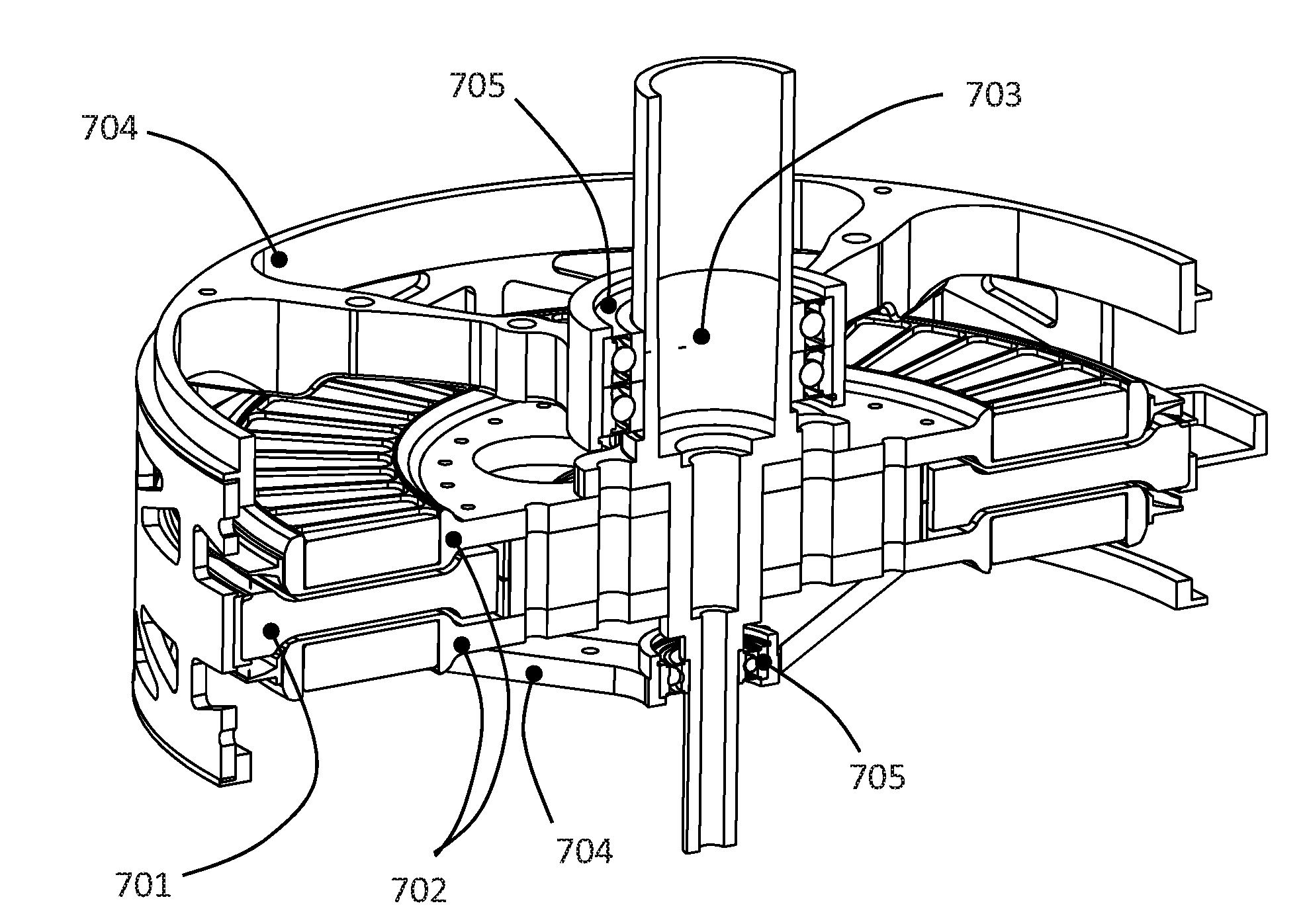
[0046]The invention described herein includes a rotor for an axial flux permanent magnet brushless electrical machine using a Halbach array of magnets in the rotor. Such an electrical machine will of course require a stator along with necessary electrical, electronic, and power-related components so as to form a working machine. It is to be understood that the preferred embodiment represents a complete electrical machine including rotor(s), at least one stator, a housing, a shaft, and bearings, though a frameless electrical machine formed solely of rotor plates and the stator also constitutes an embodiment of the invention that may be incorporated into other machines that provide the bearings, shafts, and support structures. For purposes of clarity however, details of components other than the inventive rotor structure should be understood as well known in the motor and generator art and are not discussed in detail herein.

[0047]Referring now to the drawings, it should be understood ...


PUM


Abstract

An axial flux brushless permanent magnet electrical machine having a stator and at least one rotor. The rotor includes a Halbach array of magnets with at least four magnets per magnetic cycle. The rotor magnets are contained within pockets in the rotor. The pockets are formed with magnet pocket walls being radial walls, active surface walls, and/or inactive surface walls where the walls retain the magnets within the pockets.

Description

CROSS REFERENCE TO RELATED APPLICATIONS[0001]This application claims priority to U.S. Provisional Application No. 62 / 156,556 filed on 4 May 2015.FEDERALLY SPONSORED RESEARCH OR DEVELOPMENT[0002]This invention was made with Government support under contract W31P4Q-09-C-0109 awarded by the U.S. Army Aviation and Missile Command and under contract N68335-15-C-0054 awarded by the Naval Air Warfare Center Aircraft Division and under contract NNX15CC15C awarded by the NASA Shared Services Center. The Government has certain rights in the invention.FIELD OF THE INVENTION[0003]This invention generally relates to electrical machines. More specifically, the present invention relates to rotor structure of a brushless axial flux permanent magnet (PM) electrical machines.BACKGROUND OF THE INVENTION[0004]Brushless axial flux PM electrical machines (motors and alternators) have been known for many years and embodied in many practical machines. The most common types are an axial version of a salient...

Claims


Application Information

Patent Timeline
Patent Type & Authority Applications(United States)
IPC IPC(8): H02K21/24H02K1/27H02K1/30
CPCH02K21/24H02K1/2793H02K1/30H02K1/2798
Inventor RICCI, MICHAEL RICHARDSUGAR, JONATHAN GORDONPADEN, BRADLEY EVANPADEN, DAVID BRIAN
Owner LAUNCHPOINT ELECTRIC PROPULSION SYST INC
Why Eureka
Try Eureka