Method and device for determining gas component inside a transparent container

Active Publication Date: 2016-11-17
SPARKLIKE
View PDF5 Cites 0 Cited by
  • Summary
  • Abstract
  • Description
  • Claims
  • Application Information

AI Technical Summary

Benefits of technology

[0022]The absorption signal to be detected in measurements and calibration is advantageously manipulated by WMS or FMS technique, such as by scanning a sinusoidally frequency-modulated diode laser over the absorption feature of the gas component to be determined in order to strengthen the second order polynomial fitted to the non-linear curve representing the variation in the intensity of the detected beams and concentration of the gas component to be detected and/or to minimize the low-frequency noise induced.
[0023] The performance of direct absorption is often degraded by the occurrence of 1/f noise. A common way to avoid such low frequency noise of system components, for example 1/f laser excess noise, is to shift the absorption signal to a higher frequency. In TDLAS technique, this can be achieved by a modulation of the diode laser operation current. Such modulation results in a modulation of the instantaneous laser frequency. Upon interaction with the non-linear reflected intensity profile of an absorption line, this will result in a periodic modulation of the detected intensity. This allows detection of absorption signal at the fundamental modulation frequency or its overtones.
[0024]For example a sinusoidal modulation of the diode laser operation current results in a sinusoidal wavelength (and amplitude) modulation of the laser output. Interaction with a wavelength-dependent and non-li

Problems solved by technology

However, the concentration measurements of the filling gas has some drawbacks, namely for different types of filling gas a different laser source must be used, which is clearly expensive and time consuming way to measure.
Another drawback is that the gas volume inside the typical glass unit is very small, whereupon the amount of the gas to be measured is small and thereby also the absorp

Method used


Image

  • Method and device for determining gas component inside a transparent container
  • Method and device for determining gas component inside a transparent container
  • Method and device for determining gas component inside a transparent container

Examples


Embodiment Construction

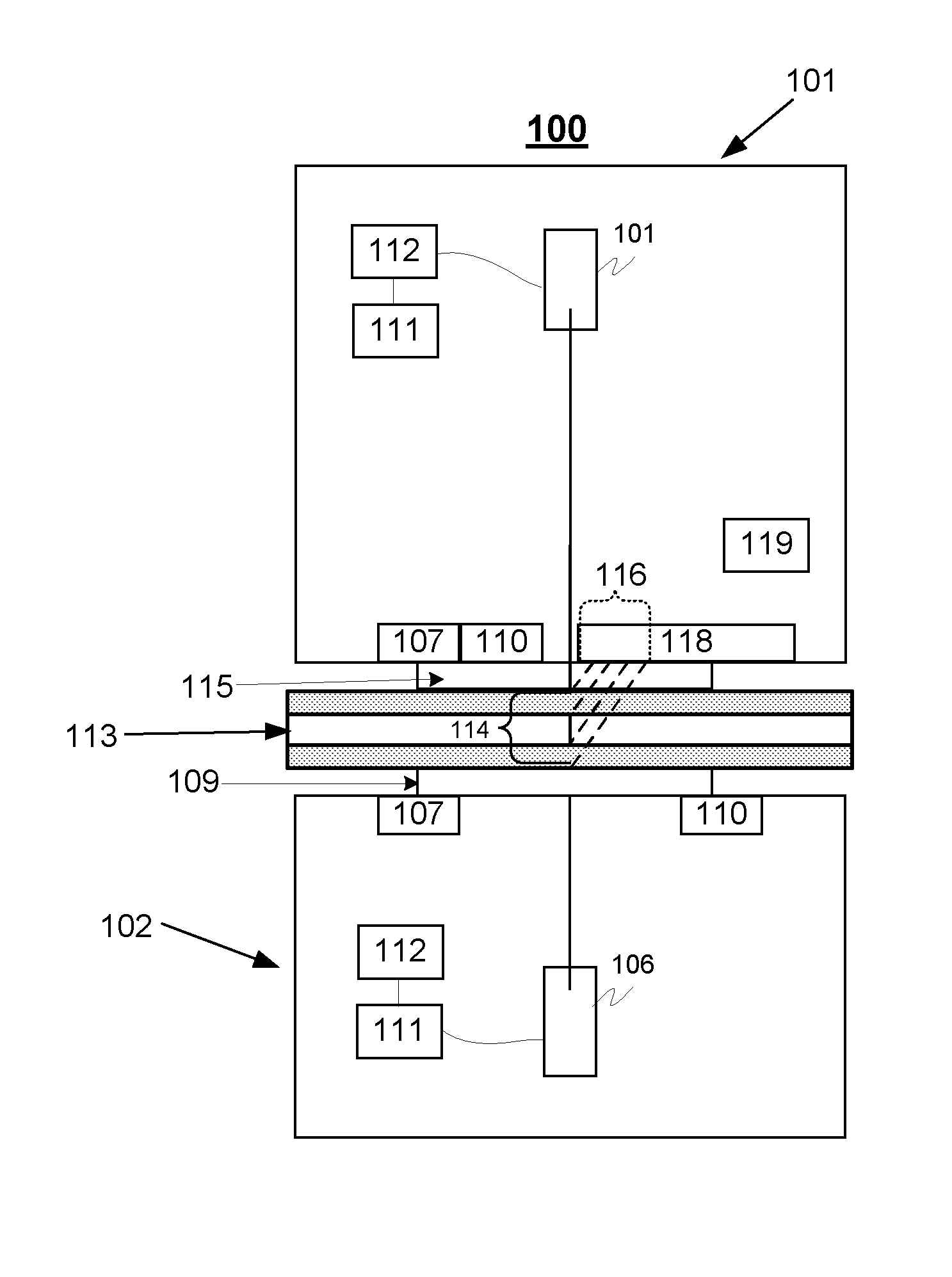
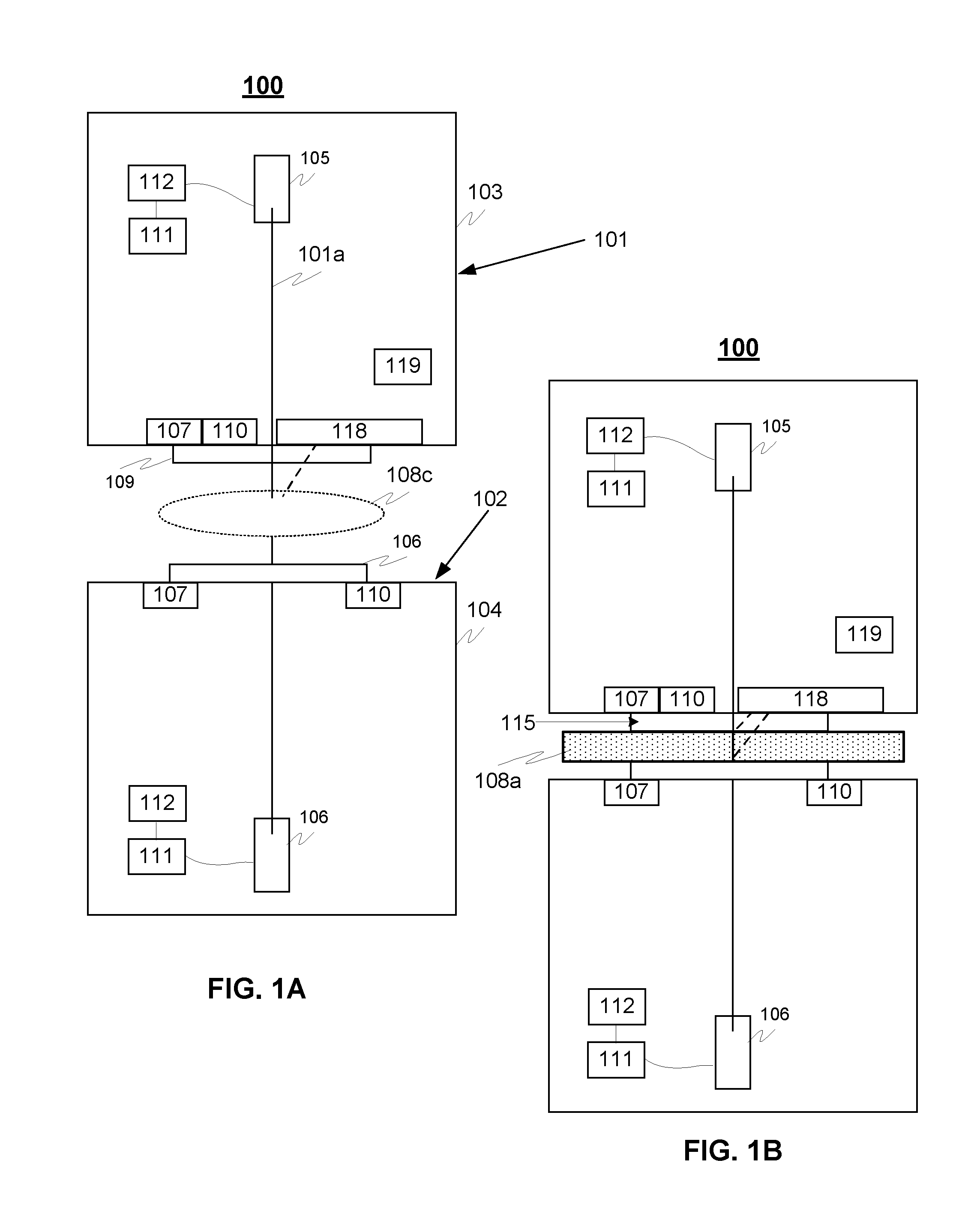
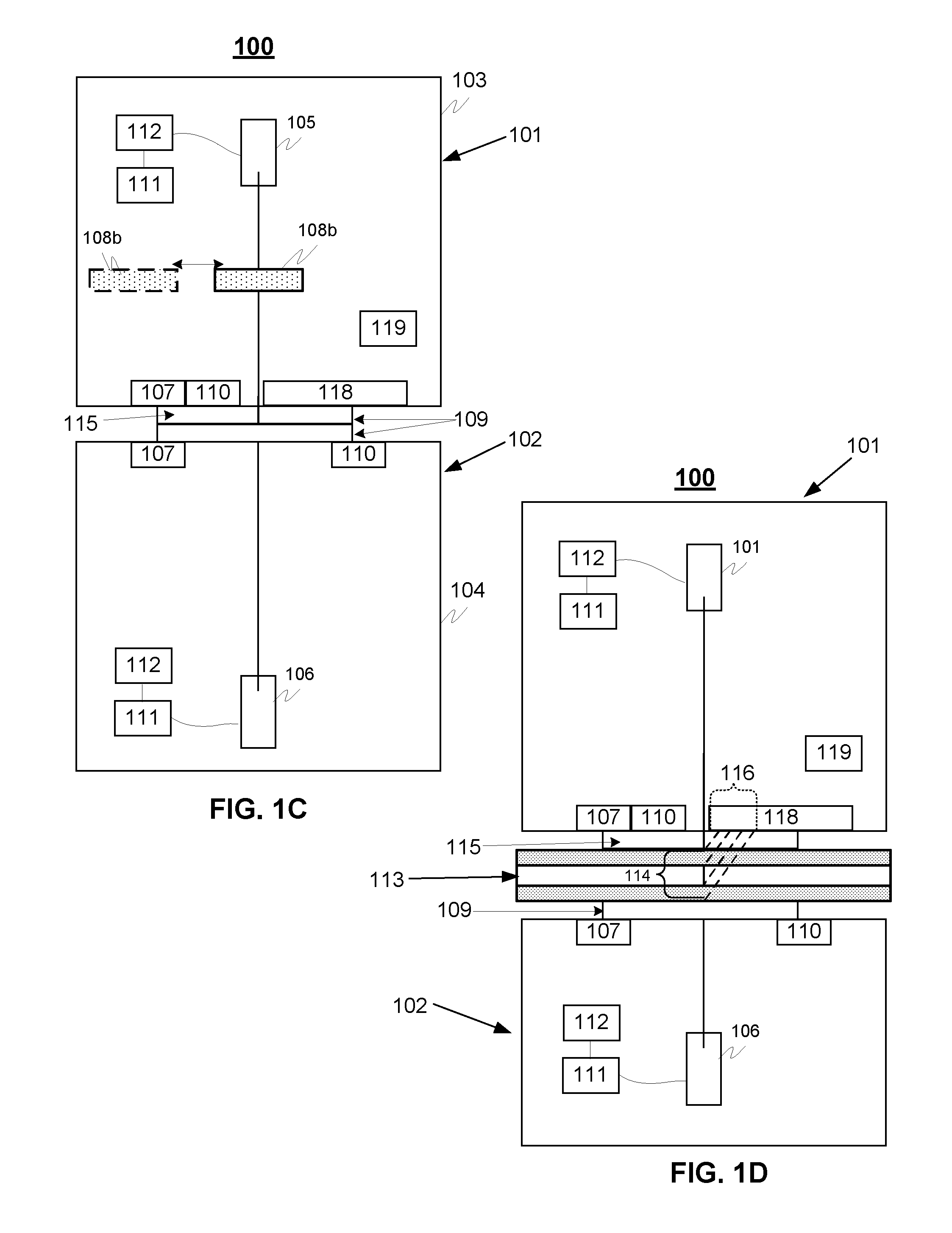
[0030]FIGS. 1A-1D illustrates principles of exemplary device 100 according to an advantageous embodiment of the invention, wherein the device comprises an emitting unit 101 and detection unit 102. The laser beam emitting unit comprises advantageously a laser source 105 for emitting laser beam towards the detecting unit 102, as well as also towards said determination space 113 when performing the determination. The detecting unit 102 comprises a detector 106 for detecting transmission of the emitted laser beams travelled through said determination space, for example. In addition the device comprises also a calibration mode, whereupon the laser beam emitted is configured to be travelled through a calibration space.

[0031]It is to be noted that the device or units 101, 102 advantageously comprises also suitable optical means (not shown) emitting and collimating the emitted beam 101a to the determination or calibration space, as well as to collect the beams from the determination or cali...


PUM


Abstract

A device for non-invasively determining existence of a gas component of interest inside a determination space of a glass unit comprises a laser beam emitting unit comprising a laser source for emitting laser beam towards said measuring space and detecting unit comprising a detector for detecting transmission of said emitted laser beams travelled through said space. The device is configured to measure in a calibration mode locations of at least one reference peak of at least same gas component as to the determined inside the determination space. The emitted laser beam is configured to travel through a calibration space having at least the gas component of interest, and the detecting means is configured essentially to detect or image said beam transmitted through said calibration space. The device is also configured to be moved so to receive said determination space between the laser beam emitting unit and detecting unit for a determining purpose of the existence of the interest gas component inside said determination space.

Description

TECHNICAL FIELD OF THE INVENTION[0001]The invention relates to a method and device for determining an interest gas component in particularly inside a glass unit of one or several separate cavities, such as insulating glass units, IGUs, or any other similar transparent container.BACKGROUND OF THE INVENTION[0002]In the glass manufacturing process glass sheets (known as float glass) can be combined with different kind of elements, such as coated or tempered layers to create glass panes for different purposes having specific properties. For example, insulating glass units, IGUs, are constructed typically with a configuration having two or more glass sheets with a closed space in between the sheets, where the closed space is filled with gas with low thermal conductivity, such as Argon, Xenon, Krypton Nitrogen or mixture of those. There is need in the industry to check the quality of the glass unit and ensure that there is no leakage, so that the filling gas has not leaked away.[0003]Diff...

Claims


Application Information

Patent Timeline
IPC IPC(8): G01N21/39G01J3/433
CPCG01N21/39G01J3/4338G01J3/433G01N21/274G01N2021/399
Inventor NIIRANEN, KAINIEMI, MIIKKAELSYRJALAHTI, MIKKO
Owner SPARKLIKE
Why Eureka
Try Eureka