
Phase correction in a doherty power amplifier

a technology of phase correction and power amplifier, which is applied in the direction of amplifier types, amplifiers with semiconductor devices/discharge tubes, amplifiers, etc., can solve the problems of power efficiency tending to worsen and power decreasing

Active Publication Date: 2016-11-17
NXP USA INC
View PDF1 Cites 24 Cited by
  • Summary
  • Abstract
  • Description
  • Claims
  • Application Information

AI Technical Summary

Benefits of technology

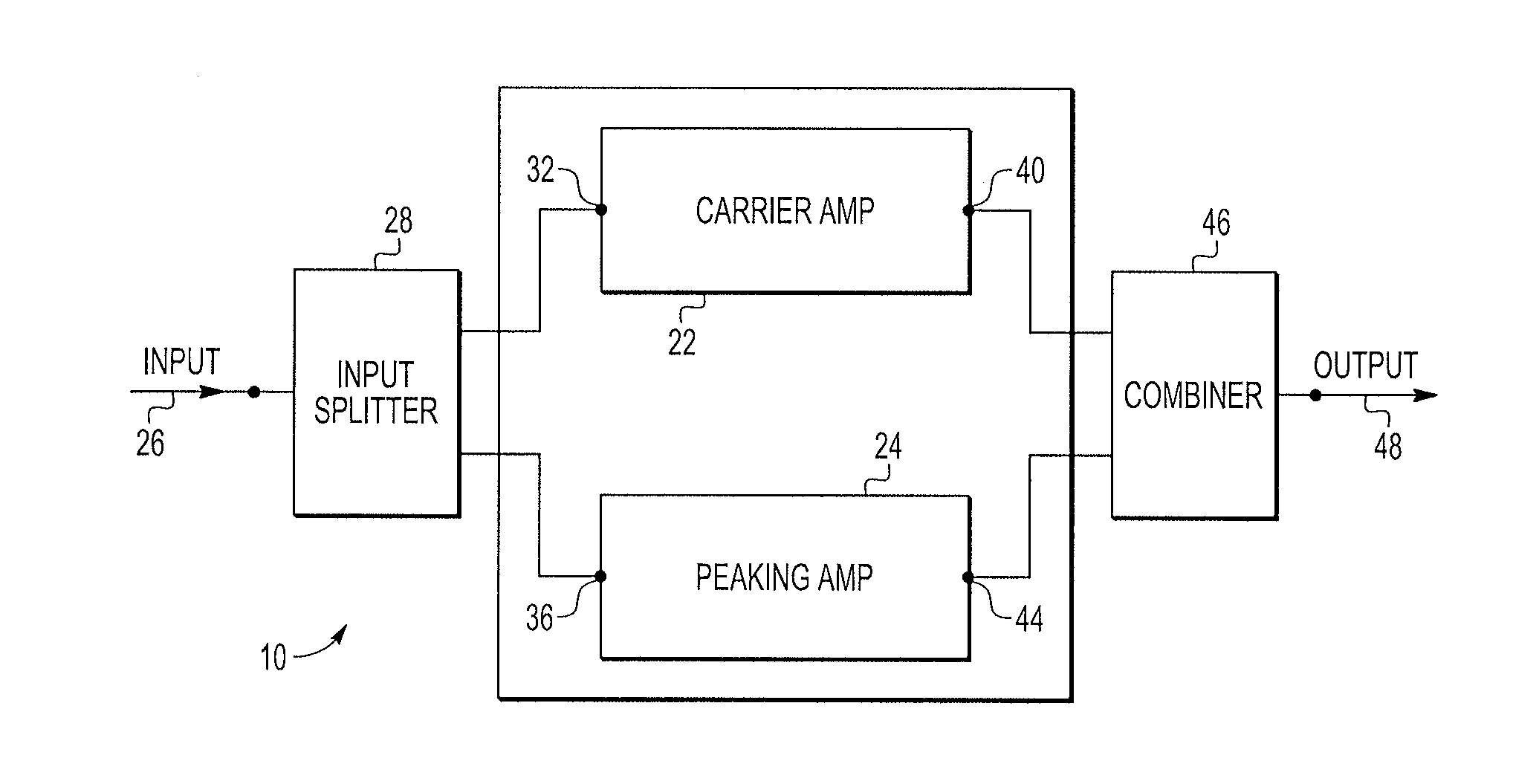
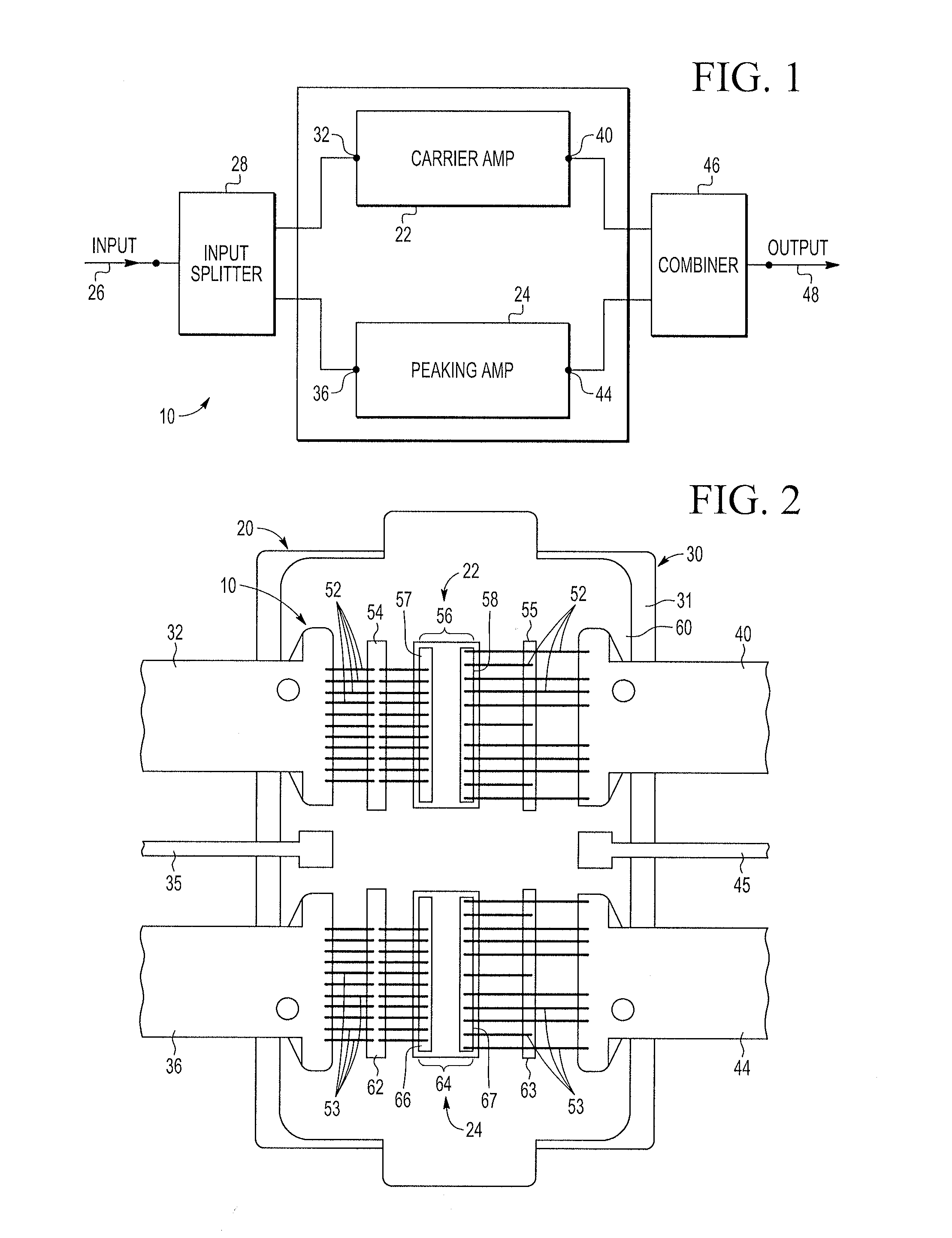
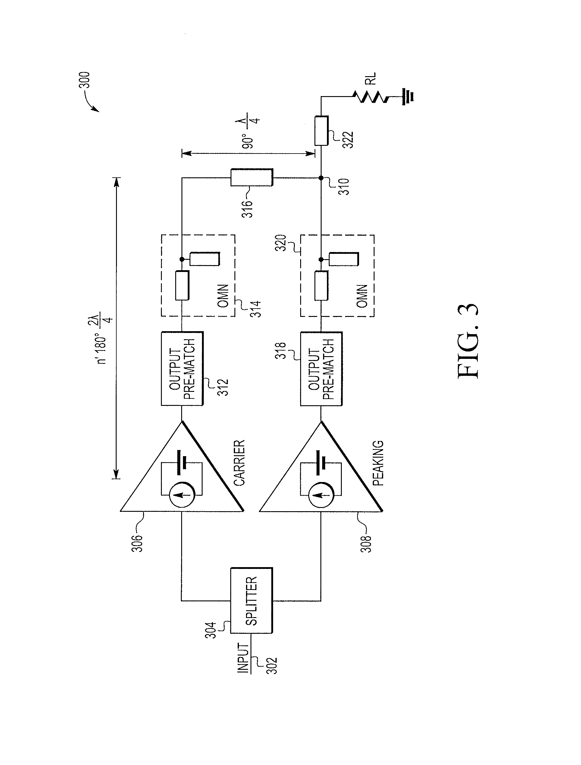
The present patent is about improving the performance and reducing the size of packaged power amplifiers by using a Doherty amplifier architecture with a phase advance network. The technical effect of this patent is to provide better phase correction in the amplifier to achieve a desired output match between the amplifier and the output combining node. This can improve the efficiency and power output of the amplifier, especially at high output power. The patent also describes the construction and operation of the Doherty amplifier, as well as the use of the phase advance network in a Doherty amplifier with multiple peaking paths. Overall, the patent aims to enhance the performance and reduce the size of Doherty amplifiers in various applications where low cost, low weight, and small volume are desired.

Problems solved by technology

However, power efficiency tends to worsen as output power decreases.

Method used


Image

  • Phase correction in a doherty power amplifier
  • Phase correction in a doherty power amplifier
  • Phase correction in a doherty power amplifier

Examples


Embodiment Construction

[0018]The following detailed description is exemplary in nature and is not intended to limit the invention or the application and uses of the same. Furthermore, there is no intention to be bound by any expressed or implied theory presented in the preceding technical field, background, or the following detailed description.

[0019]The present embodiments may be used to improve the performance and reduce the package size of packaged power amplifiers. The power amplifiers may be used in base station power amplifiers, cell phones, other portable devices, and other apparatus or devices dependent upon semiconductor packages, where low cost, low weight, and small volume may be desired. The embodiments described herein may provide enhanced phase correction in either or both of the carrier path and peaking path amplifiers of a Doherty amplifier. The embodiments may also provide enhanced phase correction in multiple peaking paths of a Doherty amplifier having three or more amplification paths.

[...


PUM


Abstract

In various embodiments, a semiconductor package includes a carrier amplifier connected to a first output of a power divider, and a first output matching network connected to the carrier amplifier and an output combining node. The first output matching network exhibits a phase delay during operation of the carrier amplifier. The semiconductor package includes a phase advance network connected to the first output matching network. The phase advance network is configured to offset at least a portion of the phase delay of the first output matching network. The semiconductor package includes a peaking amplifier connected to a second output of the power divider and the output combining node, and a second output matching network connected to the peaking amplifier.

Description

BACKGROUND[0001]1. Field of Use[0002]The present disclosure relates generally to power amplifiers, and more specifically, to power amplifiers utilizing phase advancement to achieve a desired phase correction on one or more paths of the amplifier.[0003]2. Description of the Related Art[0004]Wireless communication systems often employ power amplifiers for increasing the power of a high frequency signal. In a wireless communication system, a power amplifier is usually the last amplifier in a transmission chain (i.e., the output stage). High gain, high linearity, stability, and a high level of efficiency—the ratio of radio frequency (RF) output power to direct current (DC) power—are characteristics of an ideal amplifier.[0005]In general, a high frequency power amplifier operates at maximum power efficiency when the power amplifier transmits peak output power. However, power efficiency tends to worsen as output power decreases. Recently, Doherty power amplifier architectures have been th...

Claims


Application Information

Patent Timeline
IPC IPC(8): H03F1/02H03F3/21H03F3/19
CPCH03F1/0288H03F3/19H03F2203/21106H03F2200/451H03F3/211H03F1/565H03F3/195H03F2200/171H03F2200/387H03F2200/391
Inventor AHMED, MARUFSTAUDINGER, JOSEPH
Owner NXP USA INC
Learn More