Vibration damping device for a vehicle body
- Summary
- Abstract
- Description
- Claims
- Application Information
AI Technical Summary
Benefits of technology
Problems solved by technology
Method used
Image
Examples
first preferred embodiment
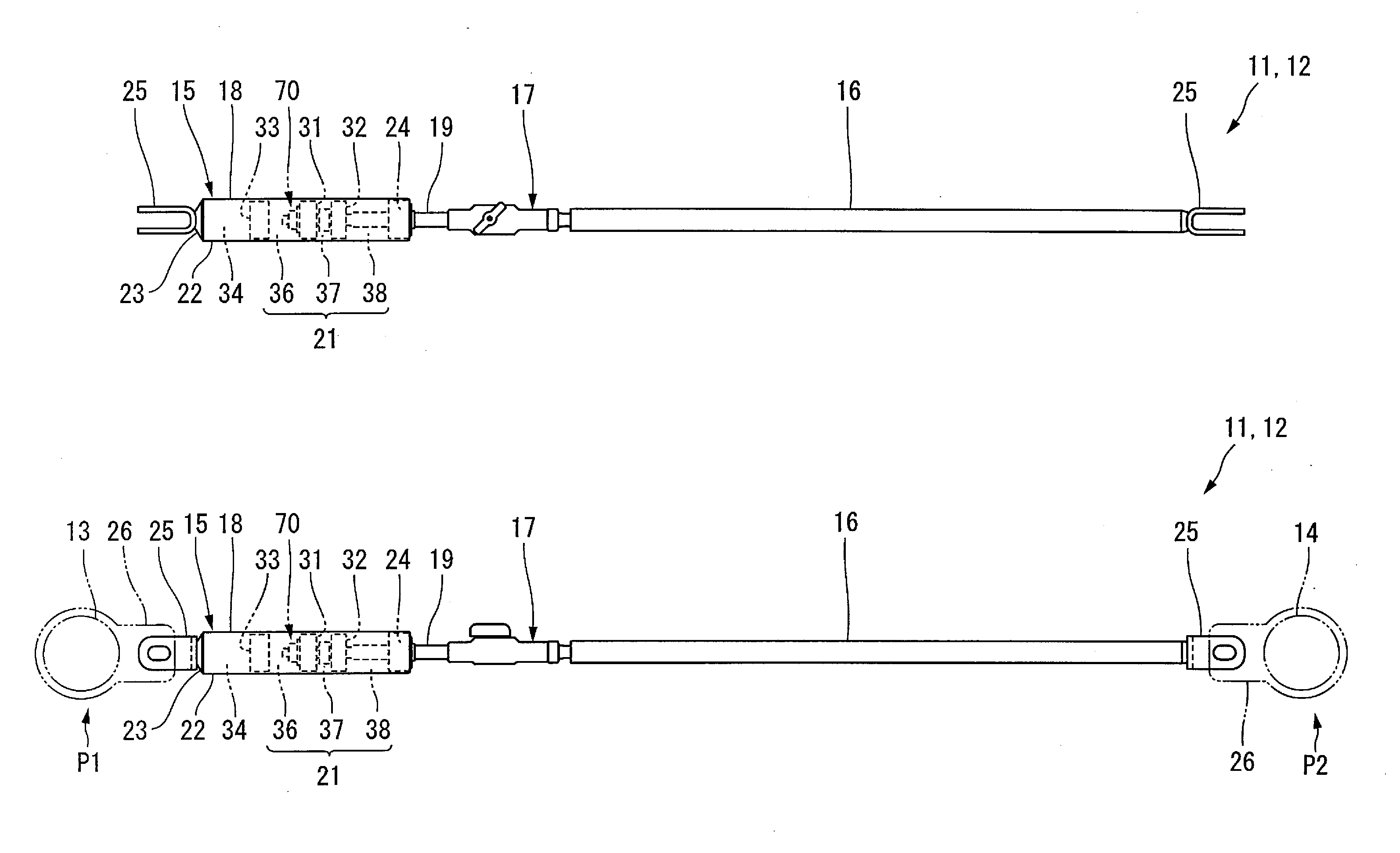
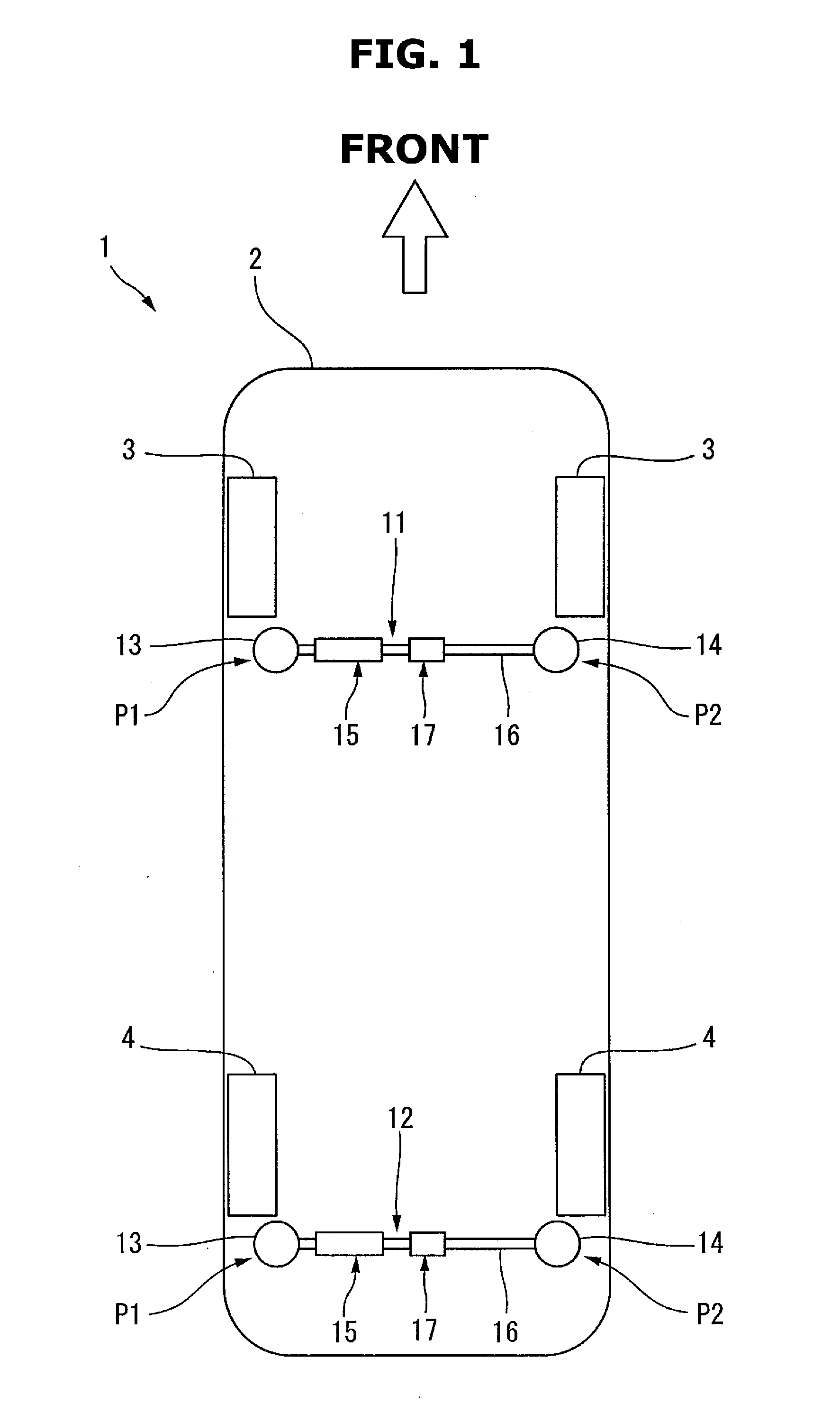
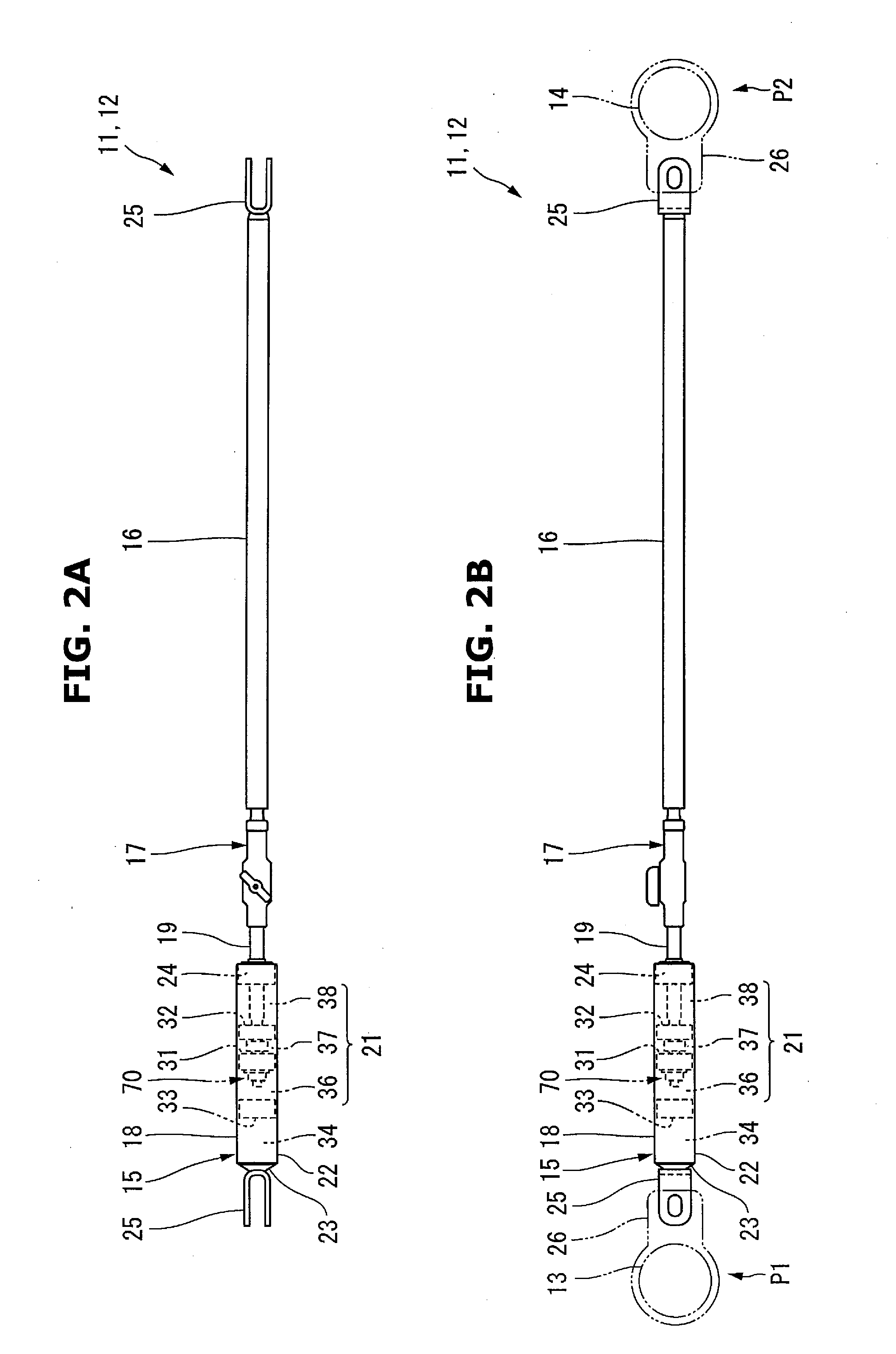
[0054]A vibration damping device for a vehicle body according to a preferred embodiment of the present invention will now be described in detail with reference to FIGS. 1 to 10.
[0055]A vehicle 1 shown in FIG. 1 is, for example, a passenger car that an occupant (not shown) drives to travel. A vehicle body 2 of the vehicle 1 is provided with a left-and-right pair of front wheels 3 and a left-and-right pair of rear wheels 4.
[0056]The vehicle body 2 of this type includes a frameless body made of, for example, high-tensile steel. The vehicle body 2 elastically deforms according to an external force applied at the time of traveling and vibrates in, for example, the side-to-side and back-and-forth directions. Examples of the external force that generates vibrations are a force applied to the vehicle body 2 when the front wheels 3 and the rear wheels 4 run on uneven spots and a force received from vibrations from an engine (not shown).
[0057]To damp the unwanted vibrations of the vehicle bod...
second preferred embodiment
[0165]An on-off valve and an operation mechanism may be constructed as shown in FIGS. 12 to 18. The same reference numerals as described with reference to FIGS. 1 to 11 denote the same or similar members in FIGS. 12 to 18, and a detailed description thereof will appropriately be omitted. A vibration damping device for a vehicle body according to the present preferred embodiment is different from the vibration damping device for a vehicle body described in the first preferred embodiment only in the on-off valve and the operation mechanism.
[0166]An on-off valve 111 shown in FIG. 12 is of a rotation type that pivots with respect to an axis C of a piston rod 19 as the center. The on-off valve 111 includes a shaft portion 112 inserted into a through hole 65 of the piston rod 19, and an expanded diameter portion 113 provided at one end of the shaft portion 112.
[0167]The shaft portion 112 includes a columnar portion 112a having a columnar shape and is located on the axis of a second piston...
third preferred embodiment
[0196]An operation mechanism used to operate an on-off valve may be constructed as shown in FIG. 22. The same reference numerals as described with reference to FIGS. 1 to 21 denote the same or similar members in FIG. 22, and a detailed description thereof will appropriately be omitted.
[0197]A vibration damping device for a vehicle body according to the present preferred embodiment is different from the vibration damping device for a vehicle body described in the first preferred embodiment only in the operation mechanism.
[0198]An operation element 141 of an operation mechanism 76 shown in FIG. 22 is a pivot-type handle as shown in FIGS. 8 and 9 or a pivot-type lever as shown in FIG. 19. One end of an operation wire 142 is connected to the operation element 141. The other end of the operation wire 142 is connected to an input member 143 spaced apart from a first mounting position P1 or a second mounting position P2 of the vehicle body. Although not illustrated, the input member 143 ma...
PUM
 Abstract
Description
Claims
Application Information
 - R&D
- Intellectual Property
- Life Sciences
- Materials
- Tech Scout
- Unparalleled Data Quality
- Higher Quality Content
- 60% Fewer Hallucinations
Browse by: Latest US Patents, China's latest patents, Technical Efficacy Thesaurus, Application Domain, Technology Topic, Popular Technical Reports.
© 2025 PatSnap. All rights reserved.Legal|Privacy policy|Modern Slavery Act Transparency Statement|Sitemap|About US| Contact US: help@patsnap.com


