
System and method for powering on-road electric vehicles via wireless power transfer

a technology of wireless power transfer and electric vehicles, applied in the field of wireless power transfer systems and methods, can solve the problems of inefficiency of wpt process, non-tracked vehicles over the air, unlimited current and destruction of power receiver circuits

Active Publication Date: 2016-11-24
ELECTREON WIRELESS LTD
View PDF8 Cites 13 Cited by
  • Summary
  • Abstract
  • Description
  • Claims
  • Application Information

AI Technical Summary

Benefits of technology

The present invention relates to a power request system that sends a signal to a device to request power. The signal can generate an alternating current in the device, which can be detected using phase detection. The technical effect of this invention is an improved and efficient way to request power from a device.

Problems solved by technology

Powering non-tracked vehicles over the air pose many challenges.
Since a non-tracked vehicle can move lateral to the direction of advancement, there is a danger of the inductance circuits on the power transmitter side (road) and the inductance circuits on the power receiver side (vehicle) become non-overlapping and thus the WPT process becomes inefficient.
Another challenge is to deal with potential radiation hazards due to the coils positioned right under the road.
Yet another challenge is to regulate the current supplied by the network to the vehicle despite a varying load.
Unregulated current at the power receiver (vehicle) may lead to unlimited current and destruction of the power receiver circuits.

Method used


Image

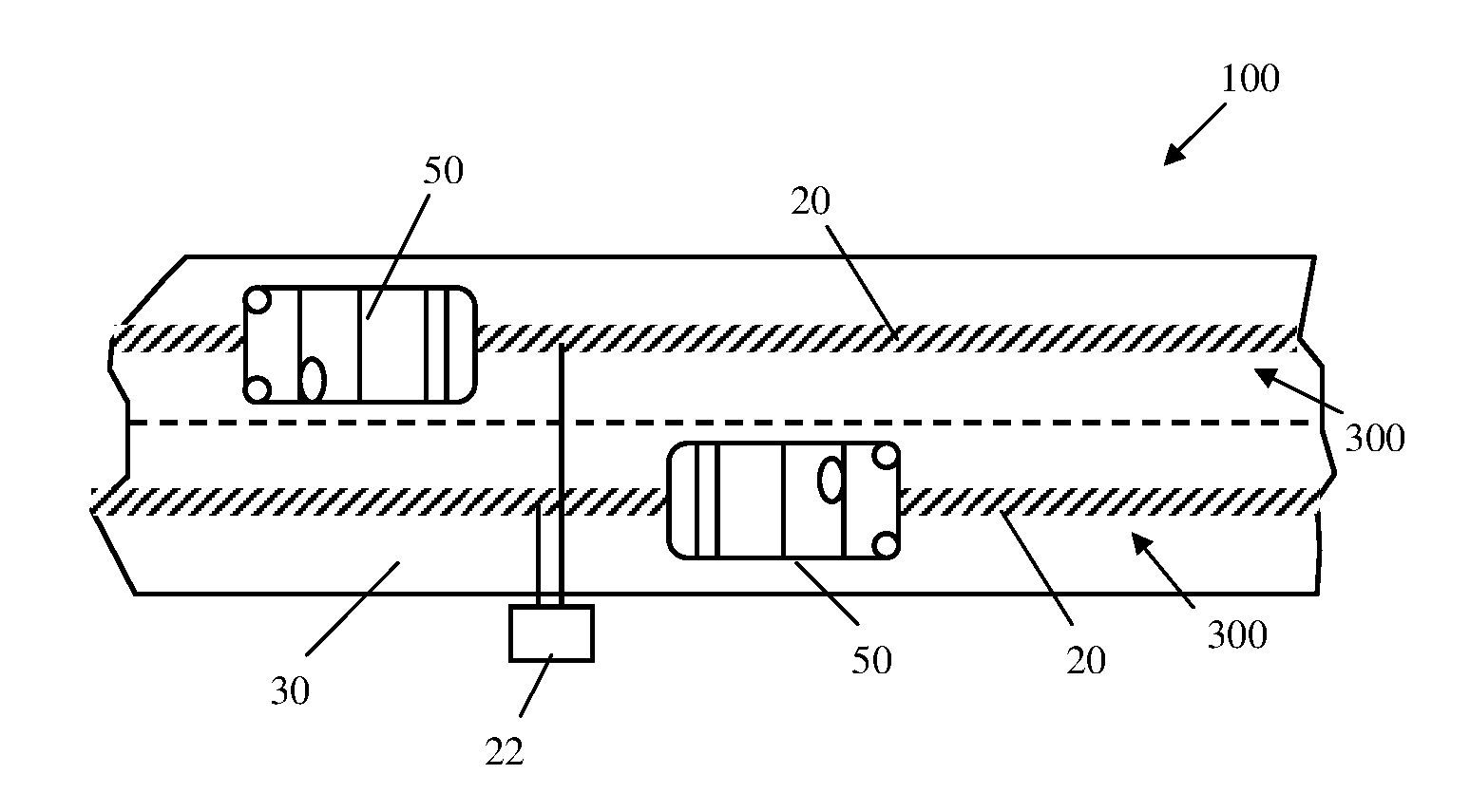
  • System and method for powering on-road electric vehicles via wireless power transfer
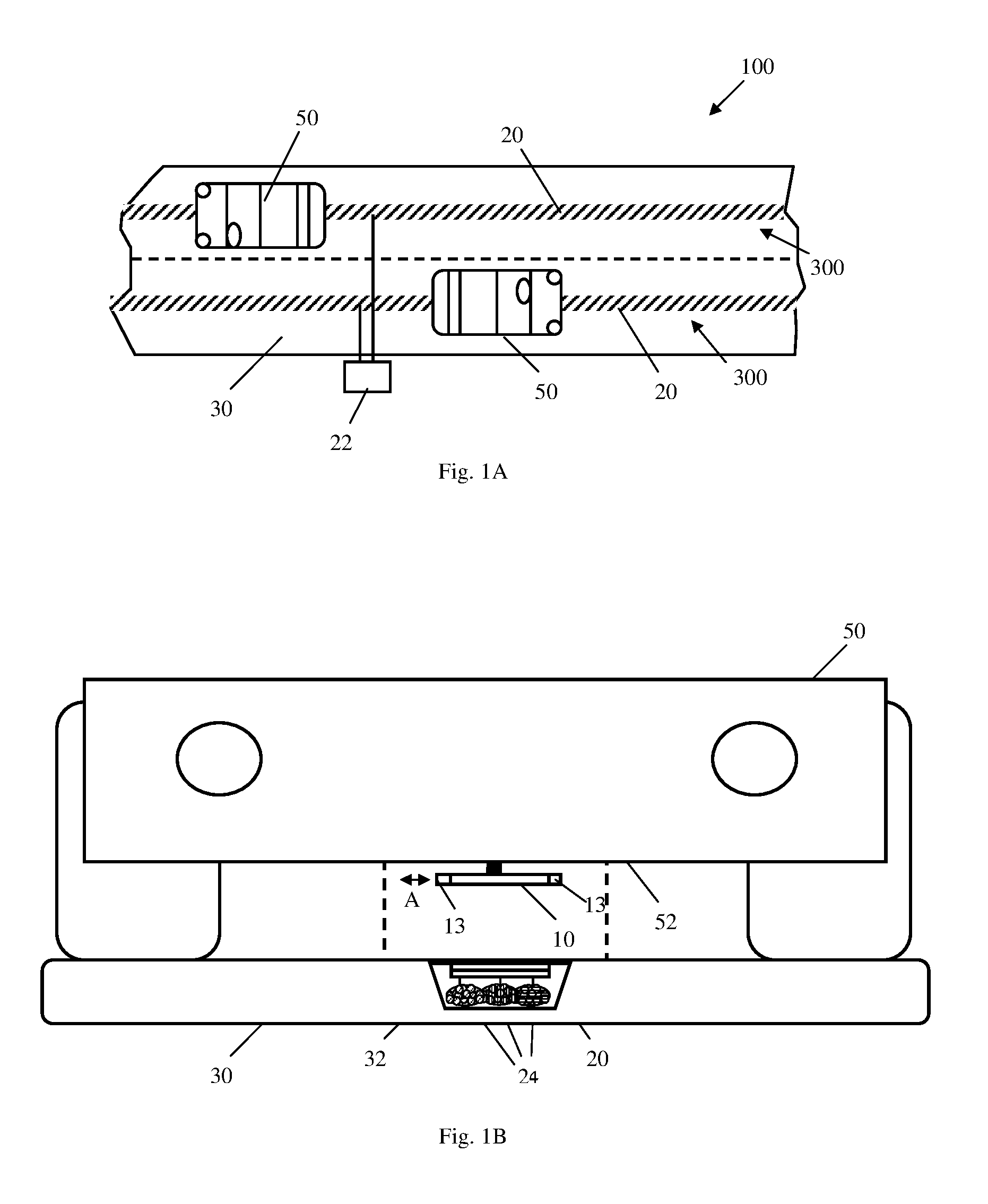
  • System and method for powering on-road electric vehicles via wireless power transfer
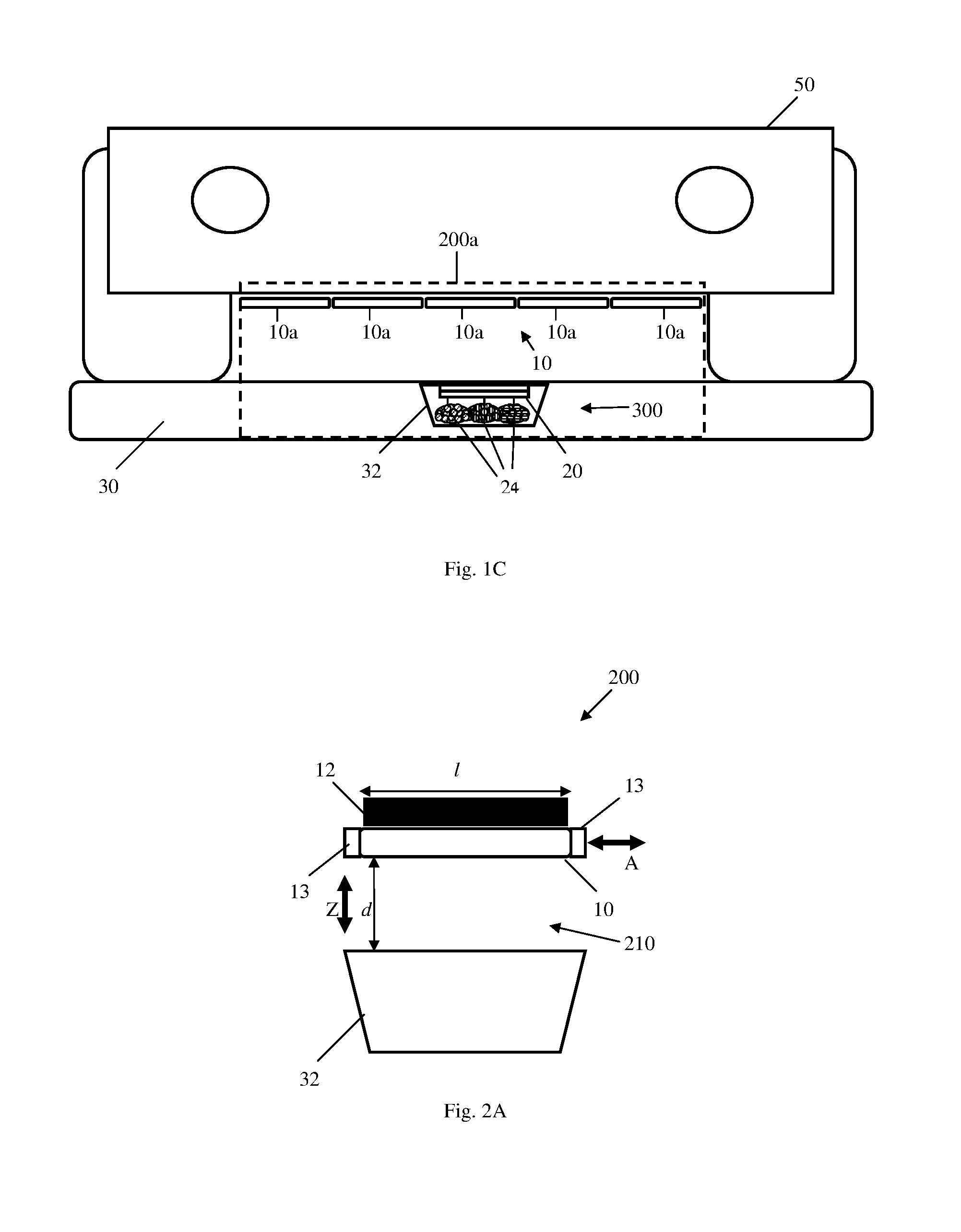
  • System and method for powering on-road electric vehicles via wireless power transfer

Examples


Embodiment Construction

[0054]In the following detailed description, numerous specific details are set forth in order to provide a thorough understanding of the invention. However, it will be understood by those skilled in the art that the present invention may be practiced without these specific details. In other instances, well-known methods, procedures, and components, modules, units and / or circuits have not been described in detail so as not to obscure the invention.

[0055]A system and method for charging an electric vehicle on a road, according to some embodiments of the present invention, may enable powering a vehicle while moving on a road. Certain sections of a road may include a charge-inducing infrastructure, which may power a vehicle moving upon it. Thus, the vehicle's chargeable battery may be used for traveling in other road sections that does not include such infrastructure. For example, the size of the vehicle's chargeable battery, which may be used for traveling in other road sections, may b...


PUM

PropertyMeasurementUnit
frequencyaaaaaaaaaa
frequencyaaaaaaaaaa
widthaaaaaaaaaa

Abstract

A system for wireless power transfer of on-road vehicles is provided herein. The system includes a plurality of base stations; a power transmission line located beneath a surface of a road having a plurality of segments, each segment having at least one pair of coils and at least one capacitor electrically connected via a switch to the coils in the segment; and at least one vehicle having at least one power receiving segment having at least two coils, connected to at least one capacitor, wherein the at least one vehicle further includes a communication transmitter configured to transmit a power requesting signal, wherein the coils of the power transmitting segment are configured to receive the power requesting signal; and wherein each of the base stations is further configured to feed a plurality of the power transmitting segments with current at a resonance frequency, responsive to the power requesting signal.

Description

CROSS REFERENCE TO RELATED APPLICATIONS[0001]This application is a Continuation-in-Part application of PCT Patent Application Number PCT / IL2014 / 051140 which was filed on Dec. 31, 2014 and claims priority from GB Patent Application No. GB1323160.0, filed on Dec. 31, 2013, both of which are incorporated herein by reference in their entirety.FIELD OF THE INVENTION[0002]The present invention relates generally to systems and methods of wireless power transfer, and in particular to such methods and system that power moving on-road vehicles.BACKGROUND OF THE INVENTION[0003]Prior to a short discussion of the related art being set forth, it may be helpful to set forth definitions of certain terms that will be used hereinafter.[0004]The term “wireless power transfer” (WPT) (also known as power-over-the-air) refers herein to the transmission of electrical energy from a power source to an electrical, such as an electrical power grid or a consuming device, without the use of conductors. In wirel...

Claims


Application Information

Patent Timeline
Patent Type & Authority Applications(United States)
IPC IPC(8): B60L11/18B60L5/00H02J50/12H03H7/38H01F38/14
CPCB60L11/182H03H7/38B60L2210/30H02J50/12B60L5/005H01F38/14H02J5/005H02J7/025B60M3/06B60M7/003B60L53/12Y02T10/7072Y02T10/70Y02T90/14Y02T90/12B60M1/10B60M3/02B60M7/00B60Y2200/91Y02T90/16
Inventor RUMBAK, HANAN
Owner ELECTREON WIRELESS LTD
Learn More