LED bulb

a technology of led bulbs and diodes, which is applied in the direction of lighting device details, light sources, lighting and heating apparatus, etc., can solve the problems of inefficient incandescent bulbs, reduced cost price of bulbs, and difficult replacement, and achieves the effect of low cos

Inactive Publication Date: 2016-11-24
SIGNIFY HLDG BV
View PDF2 Cites 14 Cited by
  • Summary
  • Abstract
  • Description
  • Claims
  • Application Information

AI Technical Summary

Benefits of technology

[0017]By mounting the LEDs around a hollow tube, cooling can be provided by using a convection current air flow through the tube, in addition to thermal radiation from the tube surface. In order to achieve maximal heat transfer from the LEDs to the environment, this flow means the thermal resistance between the LEDs and the outer bulb is increased by initiating an air flow inside the bulb. This air flow is directed towards the outer envelope, so that it is subjected to ambient cooling when near the outer envelope. This design enables a simplified heat sink structure to be used, for example entirely within the light emitting part of the bulb, or it can even avoid the need for a heat sink structure at all. This enables the bulb cost to be reduced.
[0035]For the preparation of printed electronics nearly all industrial printing methods are employed. One important benefit of printed electronics is low-cost volume production. The printing technologies generally divide between sheet-based and roll to roll-based approaches but an aerosol based deposition technology may also be used.

Problems solved by technology

The replacement of conventional incandescent light bulbs with one or more LEDs is desirable because incandescent bulbs are inefficient relative to LEDs, e.g., in terms of energy use and longevity.
While it is desirable to replace incandescent light bulbs with LEDs, there are many lighting fixtures, however, where replacement is difficult because of the operating conditions.
There is however fierce competition among manufacturers of these bulbs, and a huge pressure to reduce the cost price of the bulbs.
Despite recent cost reductions, LED bulbs are still relatively expensive.
This is mainly the result of the price of the components such as the heat sinks, the LEDs, the driver, the printed circuit board (PCB), as well as the cost associated with mounting the components.
The main problem with this proposition is that such a line of LEDs is difficult to cool.
However, in the absence of a heat sink, the LED device temperature is driven up resulting in lower performance and lifetime.

Method used


Image

  • LED bulb
  • LED bulb
  • LED bulb

Examples


Embodiment Construction

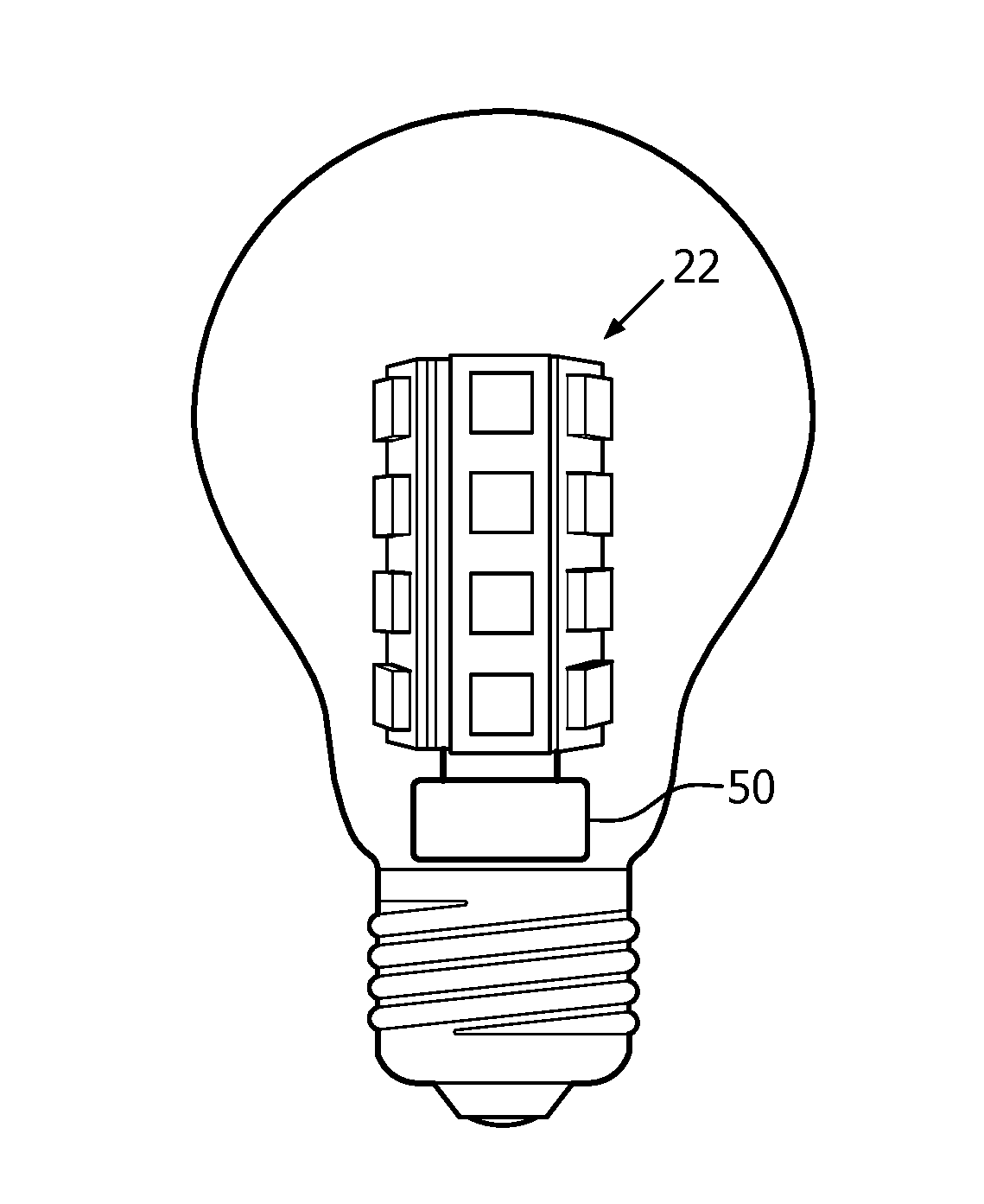
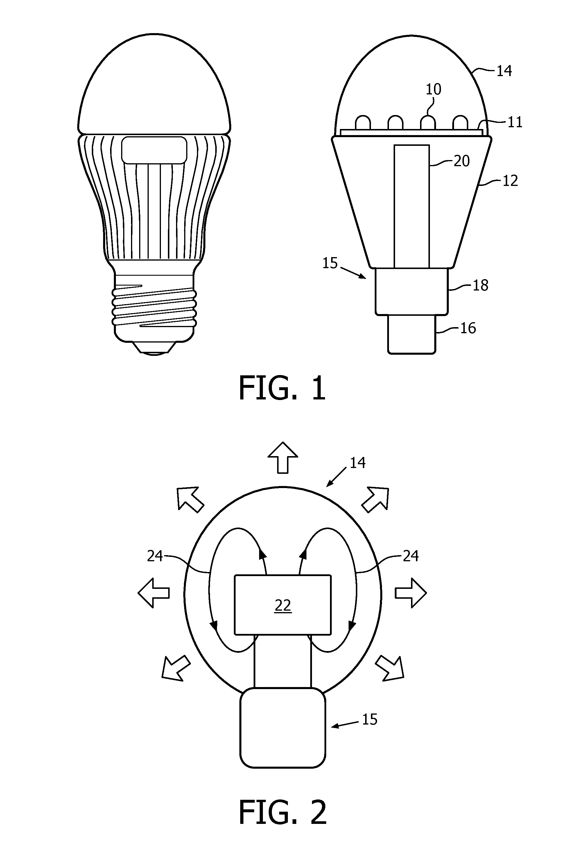
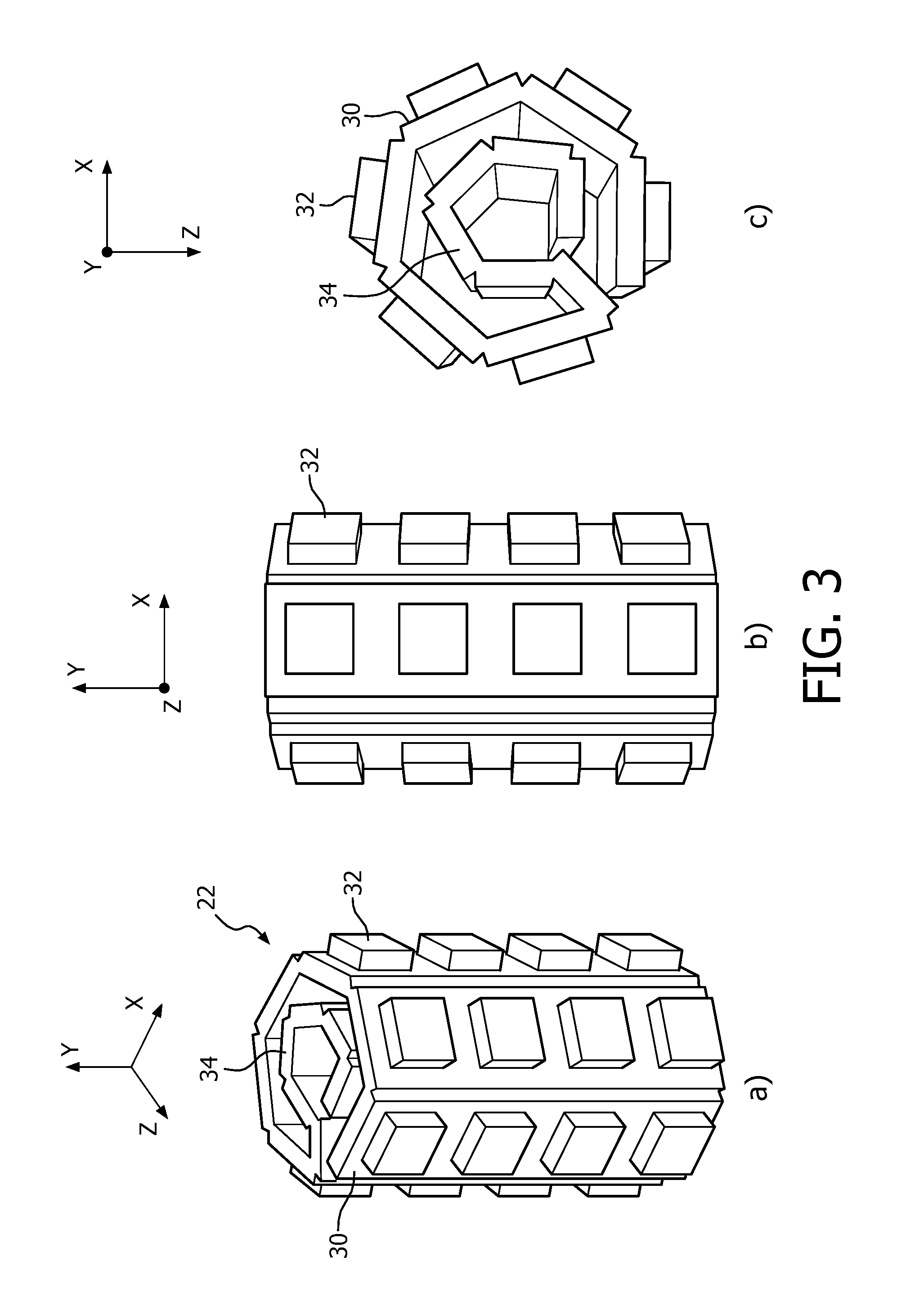
[0055]FIG. 1 shows known LED-based alternative to incandescent light bulbs, particularly A55 and A60 types. The outer appearance is shown on the left, and the internal components are shown schematically on the right. This is known as the MASTER LEDbulb available from Koninklijke Philips N.V. The blub includes a plurality of LED light sources 10 provided on a circuit board 11, which is disposed over a heat sink 12. The LEDs emit dimmable light towards a diffusing dome cover 14.

[0056]The bulb has a base which includes an electrical connector 16 and driver circuitry 18 which connects to the LEDs through conduit 20. The driver circuitry comprises an AC / DC converter that converts the AC power from the electrical connector to DC power. In this example, the driver circuitry additionally comprises dimming control circuitry, for example implemented using pulse width modulation (PWM). However, dimming control is not an essential function.

[0057]The heat sink 12 is a significant contributor to ...


PUM


Abstract

An LED light bulb has LEDs (32) mounted on a tubular carrier (22) with open ends. The tube (22) functions as a chimney to promote cooling by creating convection currents through the chimney. The cooling can be entirely passive or it may be active by incorporating a fan (50).

Description

FIELD OF THE INVENTION[0001]The present invention relates generally to a light emitting diode (LED) bulb, and in particular to cooling an LED lamp.BACKGROUND[0002]Recently there has been a trend in replacing conventional incandescent light bulbs with LED bulbs. The replacement of conventional incandescent light bulbs with one or more LEDs is desirable because incandescent bulbs are inefficient relative to LEDs, e.g., in terms of energy use and longevity.[0003]LED bulbs also offer the possibility to employ two or more groups or “channels” of LEDs which produce light of different colors, each controllably supplied with predetermined currents to enable the generation and mixing of light to produce general illumination with desired attributes or a desired lighting effect. Thus, LEDs offer more versatile lighting solutions.[0004]While it is desirable to replace incandescent light bulbs with LEDs, there are many lighting fixtures, however, where replacement is difficult because of the ope...

Claims


Application Information

Patent Timeline
Patent Type & Authority Applications(United States)
IPC IPC(8): F21K9/237F21K9/235F21V3/02F21V23/00F21V29/83F21K9/232F21K9/238
CPCF21K9/237F21K9/232F21K9/235F21Y2115/10F21V23/005F21V29/83F21V3/02F21K9/238F21K9/90F21V29/60F21V29/78F21Y2107/40
Inventor DEKKER, TIMSHI, HAOYANGEGGINK, HENDRIK JANGU, WEIJIANG, QUINGQING
Owner SIGNIFY HLDG BV
Why Eureka
Try Eureka