
Fluidized bed gas distributor system for elevated temperature operation

a distributor system and fluidized bed technology, applied in lighting and heating apparatus, furnace doors, furnaces, etc., can solve the problems of direct injection of fuel into the fluidized bed by mechanism, adverse effect on the quality of products, and inability to be employed, so as to reduce or eliminate the high temperature zones, the effect of favorable heat transfer behavior of fluidized solids

Inactive Publication Date: 2006-03-16
PROCEDYNE
View PDF22 Cites 0 Cited by
  • Summary
  • Abstract
  • Description
  • Claims
  • Application Information

AI Technical Summary

Benefits of technology

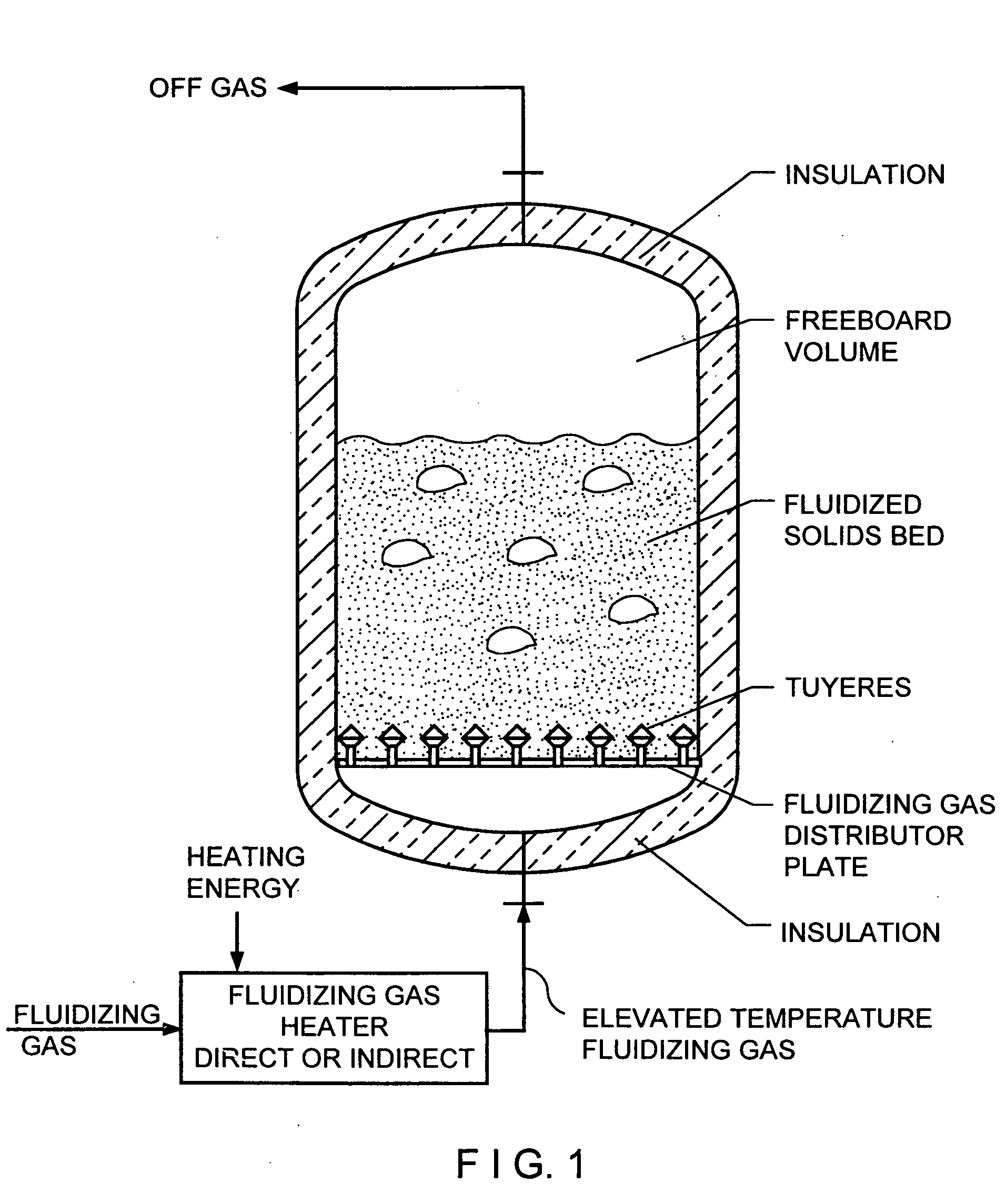
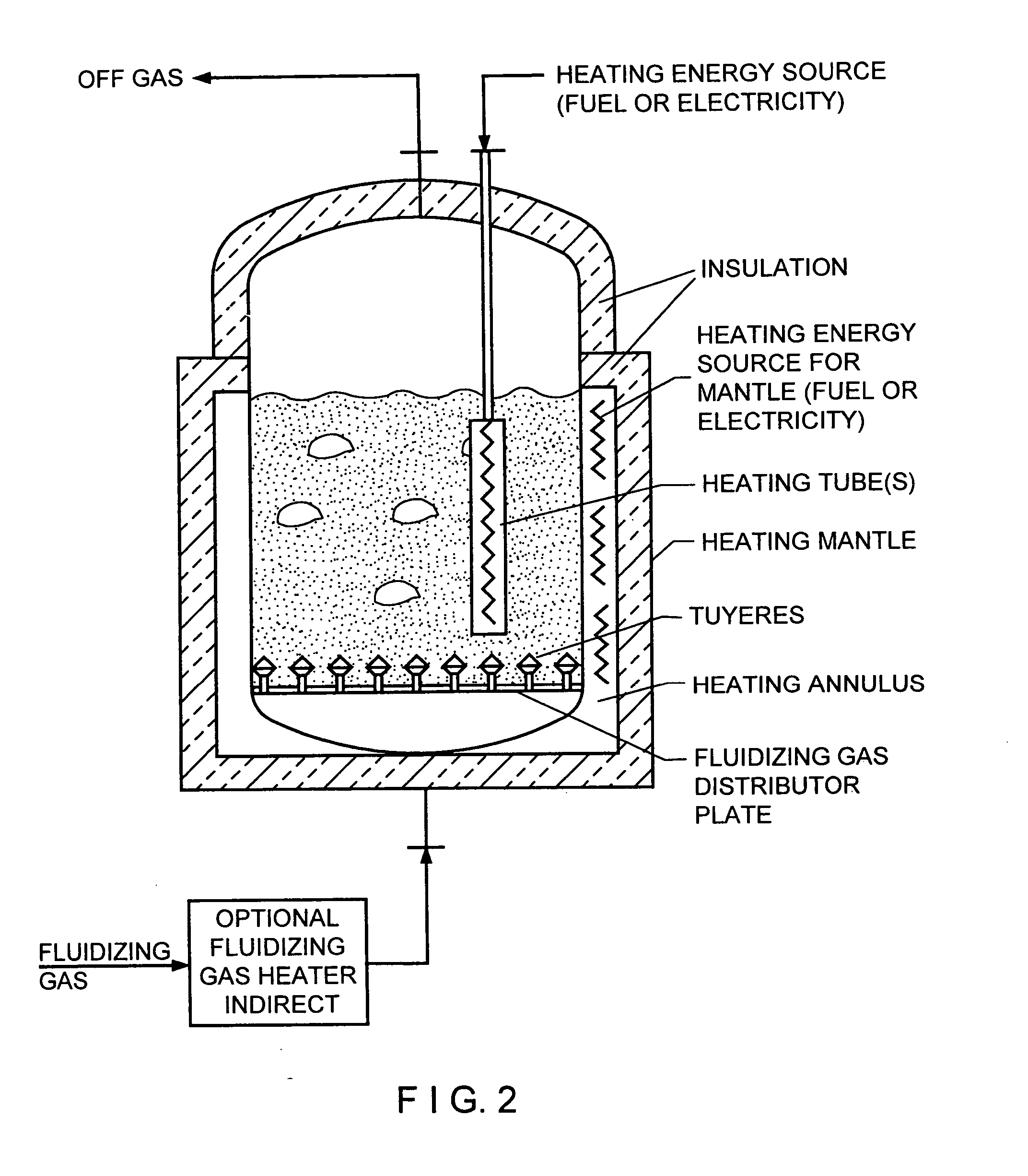
[0026] This configuration ensures that the piping array is at an elevation above the initiation of fluidization, and therefore, in the bed of fluidized solids. This results in significant indirect heat transfer from the fluidizing gas in the distribution piping through the pipe walls of the array into the fluidized bed due to the generally favorable heat transfer behavior of fluidized solids. This indirect heat transfer causes the temperature of the gas phase discharging through the tuyere distributors to be lower than the temperature of the fluidizing gas which was fed to the piping array. This condition yields a more uniform temperature at the lower part of the fluidized bed in the vicinity of the distribution tuyeres.
[0027] This gas phase distribution invention reduces or eliminates the high temperature zones in the vicinity of the distribution tuyeres which can degrade or destroy the parts being treated which are located near the lower portion of the fluid bed furnace and make it impossible to exploit the benefits of a fluid bed furnace with a directly heated energy transfer mechanism involving high temperature fluidizing gas.
[0028] This gas phase distribution arrangement has the additional advantage that the downward direction of discharge of the tuyeres reduces the tendency of particles of solids to enter the piping array through the tuyere gas phase discharge holes.

Problems solved by technology

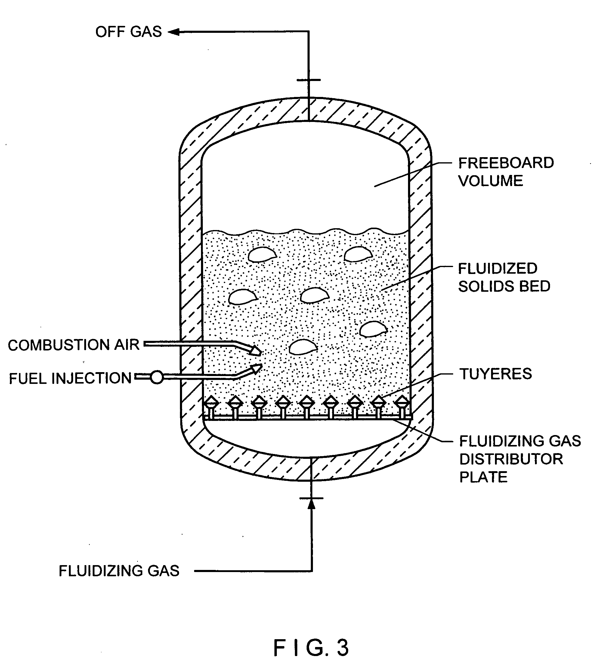
In these cases, direct injection of fuel into the fluidized solids bed by Mechanism iii, cannot be employed due to combustion gases being present in the fluidized solids bed which has an adverse effect on the quality of the products.
The maximum rate of energy transfer to the gas fluidized solids bed possible by this mechanism, is limited by the maximum temperature the furnace fluidizing gas distribution tuyere system can withstand mechanically, and the maximum fluidizing velocity that can be applied to the solids being fluidized without excessive entrainment of solids in the fluidizing gas exiting from the furnace.
The primary disadvantage to the use of Mechanism i, is that in applications requiring high rates of energy input to the gas fluidized solids, the temperature of the fluidizing gas must be significantly higher than the temperature of the fluidized solids bed.
This high temperature can in some cases, damage the parts being processed if the parts come close to, or contact a tuyere.
In addition, there are typically small shavings, pieces, or chips of aluminum which fall from the parts being processed which find their way to the bottom of the fluid bed furnace and gradually accumulate over a period of time.
When these pieces approach the vicinity of a tuyere, or contact a tuyere, they are usually melted and gradually surround the tuyeres and impede the flow of air.

Method used


Image

  • Fluidized bed gas distributor system for elevated temperature operation
  • Fluidized bed gas distributor system for elevated temperature operation
  • Fluidized bed gas distributor system for elevated temperature operation

Examples


Embodiment Construction

[0037] Turning now to the figures where like parts will be similarly numbered, FIG. 4, shows a high temperature fluidized bed furnace 10 in one typical configuration involving the processing of a major metal part. This furnace is equipped with a fluidized bed gas distributor 12. This gas distributor 12 is shown in more detail in FIG. 5 and the downward discharging tuyere generally designated 14 is shown in FIG. 6.

[0038] In this invention, high temperature fluidizing gas is distributed through the furnace 10 in a horizontal plane by a piping array 16 as shown in FIGS. 4, 5, and 6. With the discharge of the fluidizing gas from the tuyeres 14 located below the distributing piping array 16, the elevation level of initiation of fluidization of the solids is below the piping array 16. Therefore, the piping array 16 has fluidized solids bed 18 all around it, and the heat transfer rate from the piping array 16 to the bed of gas fluidized solids benefits from the typically favorable heat tr...


PUM

PropertyMeasurementUnit
temperatureaaaaaaaaaa

Abstract

A method and apparatus for the debonding and sand core removal of sand cores from cast parts, the heat treating of metal parts and the removal of organic contamination from metal parts, which is utilizing a fluid bed furnace having an improved fluidizing gas distributor which discharges fluidized gas in a downward direction away from the parts in the fluidized bed.

Description

FIELD OF THE INVENTION [0001] The present invention relates generally to the methods and apparatus for the debonding and sand core removal of sand cores from cast parts, the heat treating of metal parts and the removal of organic contamination from metal parts, and relates more specifically to an improved method and apparatus utilizing a fluid bed furnace equipped with an improved fluidizing gas distributor. BACKGROUND OF THE INVENTION [0002] In the casting of ferrous and non ferrous metal into parts, the cast part is formed by pouring the molten ferrous or non ferrous metal into a mold. When the part has internal openings or paths, sand cores are made using foundry sand and a binder to the shape of the internal openings or paths, and are positioned in the proper location in the mold. The molten metal is poured into the volume between the mold and the core(s) usually surrounding some or most of the core. When the metal solidifies, the mold is opened and the part is removed. In most ...

Claims


Application Information

Patent Timeline
Patent Type & Authority Applications(United States)
IPC IPC(8): B01J8/18C21B7/16B22D29/00B01J8/24F27B9/02F27B9/06F27B9/14F27B9/24F27B15/02F27B15/10F27B15/14F27D1/18F27D7/02
CPCB01J8/1818F27M2001/012B01J2208/00132B01J2208/0015B01J2208/00371B01J2208/00495B22D29/003F27B9/028F27B9/062F27B9/068F27B9/14F27B9/2461F27B15/02F27B15/10F27B15/14F27D2001/1891B01J8/1836
Inventor STAFFIN, H. KENNETHTRAINA, EDWARD P.RUBINO, GIOVANNI
Owner PROCEDYNE
Learn More