Method for protecting and unprotecting the fluid path in a controlled environment enclosure

a technology for controlling environment and fluid path, which is applied in the direction of dirt cleaning, heating types, biochemistry apparatuses, etc., can solve the problems of inability to fully automate without human intervention, the size and complexity of automated equipment located in the controlled environment is typically such as, and the risk of gloves being leaking, etc., to achieve the effect of reducing the risk of leaking gloves

Active Publication Date: 2016-12-01
VANRX PHARMASYST
View PDF0 Cites 23 Cited by
  • Summary
  • Abstract
  • Description
  • Claims
  • Application Information

AI Technical Summary

Benefits of technology

[0014]The inventors envision that compact and well-designed automated equipment can be operated inside closed controlled environments without the use of any gloves, eliminating thereby the risk of leaky gloves. The invention provides a method of installing a fluid path inside a controlled environment enclosure without the use of gloves. This requires the fluid path to be protected during the decontamination process and to be unprotected prior to the use of the fluid path. Furthermore the fluid path can be automatically closed after use.
[0015]The closed fluid path can be re-opened and re-used at a later time. This can be useful for continuing the use of the fluid path after unplanned events that require breaking of the integrity of the enclosed controlled environment. Additionally the closing of the fluid path can be particularly useful in situations where the fluid path has been in use for transfer of hazardous substances. After closing of the fluid path, the enclosed environment can be cleaned and decontaminated; after which the fluid path can be removed.

Problems solved by technology

Such gloves are subject to significant risk of puncture.
The automated equipment located in the controlled environment is typically of such a size and complexity that it cannot be operated fully automatically without human intervention.
Such human intervention typically requires the use of gloves with the associated risk of puncture.
Accumulation of these agents in flexible tubing and subsequent delayed release can be a major contamination problem during operation.

Method used


Image

  • Method for protecting and unprotecting the fluid path in a controlled environment enclosure
  • Method for protecting and unprotecting the fluid path in a controlled environment enclosure
  • Method for protecting and unprotecting the fluid path in a controlled environment enclosure

Examples


Embodiment Construction

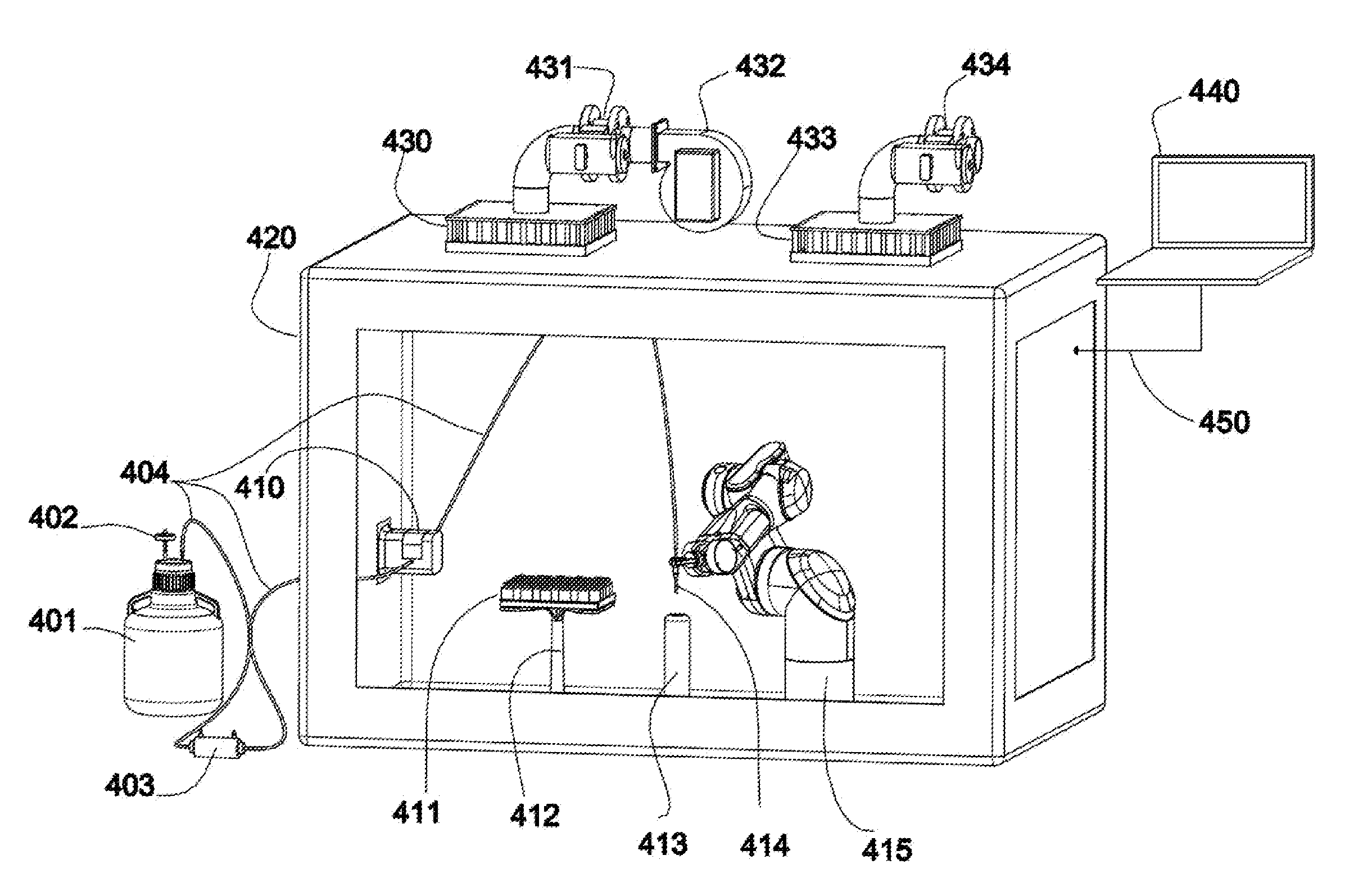
[0026]FIG. 1 shows an embodiment of an apparatus for protecting and unprotecting of a fluid path 404 in a controlled environment enclosure 420. The term “fluid” as used herein denotes any liquid, gas, liquid-gas mixtures and any mixture of solids in liquid that has fluid attributes, such as flowability or having appreciable fluidity at ambient temperature and pressure, including, without limitation, a dispersion of a solid or solids in a liquid, an emulsion, a slurry, a micro-emulsion, colloidal suspension, a suspension, a suspension of liposomes, a suspension of micelles or the like. The term “fluid path” as used herein denotes any single channel or multi channel tubing, rigid or flexible, for transporting a fluid.

[0027]A fluid path 404 starts at a container 401. The term “container” as used herein denotes any vessel suitable to hold a fluid, including without limitation any vial, syringe, ampoule, carpule, bottle, flask, beaker, bag, well in micro-well plates, well in multi-well p...


PUM

PropertyMeasurementUnit
mechanicalaaaaaaaaaa
sizeaaaaaaaaaa
gas permeabilityaaaaaaaaaa

Abstract

A controlled environment enclosure comprises a robotic arm manipulation system used to protect and unprotect a fluid path within the controlled environment enclosure. The apparatus allows the fluid path to be protected against dangerous decontamination vapors and chemicals before the controlled environment enclosure is decontaminated, the method not requiring the use of gloves or other means that degrade the integrity of the controlled environment enclosure. The apparatus similarly allows the fluid path to be unprotected for use without the use of gloves, the method not requiring the use of gloves or other means that degrade the integrity of the controlled environment enclosure when decontamination is completed. The apparatus and method allow for the protecting, unprotecting and decontaminating sequences to be automated.

Description

TECHNICAL FIELD[0001]This document relates generally to controlled environment enclosures and in particularly to a method for protecting and unprotecting the fluid path in a controlled environment enclosure.BACKGROUND[0002]Controlled environment enclosures are known in the art. Such enclosures are used, for example, for containment of hazardous materials. In other examples controlled environment enclosures are used to provide controlled environments with limited numbers of particulates.[0003]In the art controlled environment enclosures are typically fitted with ports for transfer of materials in and out of the enclosure and the ports are fitted with gloves for manual manipulation of equipment, parts or materials inside the enclosure. Such gloves are subject to significant risk of puncture.[0004]In some examples known in the art the controlled environment enclosure is also used to limit exposure to viable particulates. Such controlled environment enclosures may be required for asepti...

Claims


Application Information

Patent Timeline
Patent Type & Authority Applications(United States)
IPC IPC(8): B01L1/02B25J21/00A61L2/24A61L2/07A61L2/16
CPCB01L1/025A61L2/07A61L2/16B01L2200/0689B25J21/00B01L2200/141B01L2300/0832A61L2/24G01N35/0099G01N2035/00277C12M29/00C12M37/02C12M41/14F24F7/06B08B15/023
Inventor IMMERZEEL, JEROENPROCYSHYN, CHRISTOPHER A.PARK, STEVE SANG JOON
Owner VANRX PHARMASYST
Why Eureka
Try Eureka