
Underwater Breathing Apparatus

Inactive Publication Date: 2016-12-01
SMITH SCOTT ANDREW
View PDF19 Cites 8 Cited by
  • Summary
  • Abstract
  • Description
  • Claims
  • Application Information

AI Technical Summary

Benefits of technology

The invention is a portable and safe underwater breathing apparatus that uses a low pressure blower to provide unregulated, filtered air to the swimmer. It eliminates the use of compressors, air pumps, and air regulators, making it efficient and affordable. The apparatus has a flow of clean filtered air, eliminating unwanted contaminates or insects. The device is stable and supported by a water-resistant enclosure that keeps it out of the water even in windy or rough seas. It also uses easily replaceable and rechargeable lithium ion batteries for power. Overall, this invention provides an improved and effective way for swimmers to breathe underwater for extended periods of time.

Problems solved by technology

In other underwater breathing devices there tends to be an accumulation of water in the breathing tube and mouthpiece.
This is due to either water condensing within the breathing tube, leaky seals or water entering the air intake.
Therefore it becomes very difficult to expel the water and the purging must be done above the surface of the water.
In naturally aspirated snorkel devices the swimmer is limited to breathing at a shallow depth due to the weakness of the human diaphragm muscle to overcome water pressure.
In devices that are powered by wet cell batteries or internal combustion engines the risk of air contamination exists.
Many underwater breathing devices use compressed, unfiltered air that can be problematic for the air regulator and the swimmer.

Method used


Image

  • Underwater Breathing Apparatus
  • Underwater Breathing Apparatus
  • Underwater Breathing Apparatus

Examples


Embodiment Construction

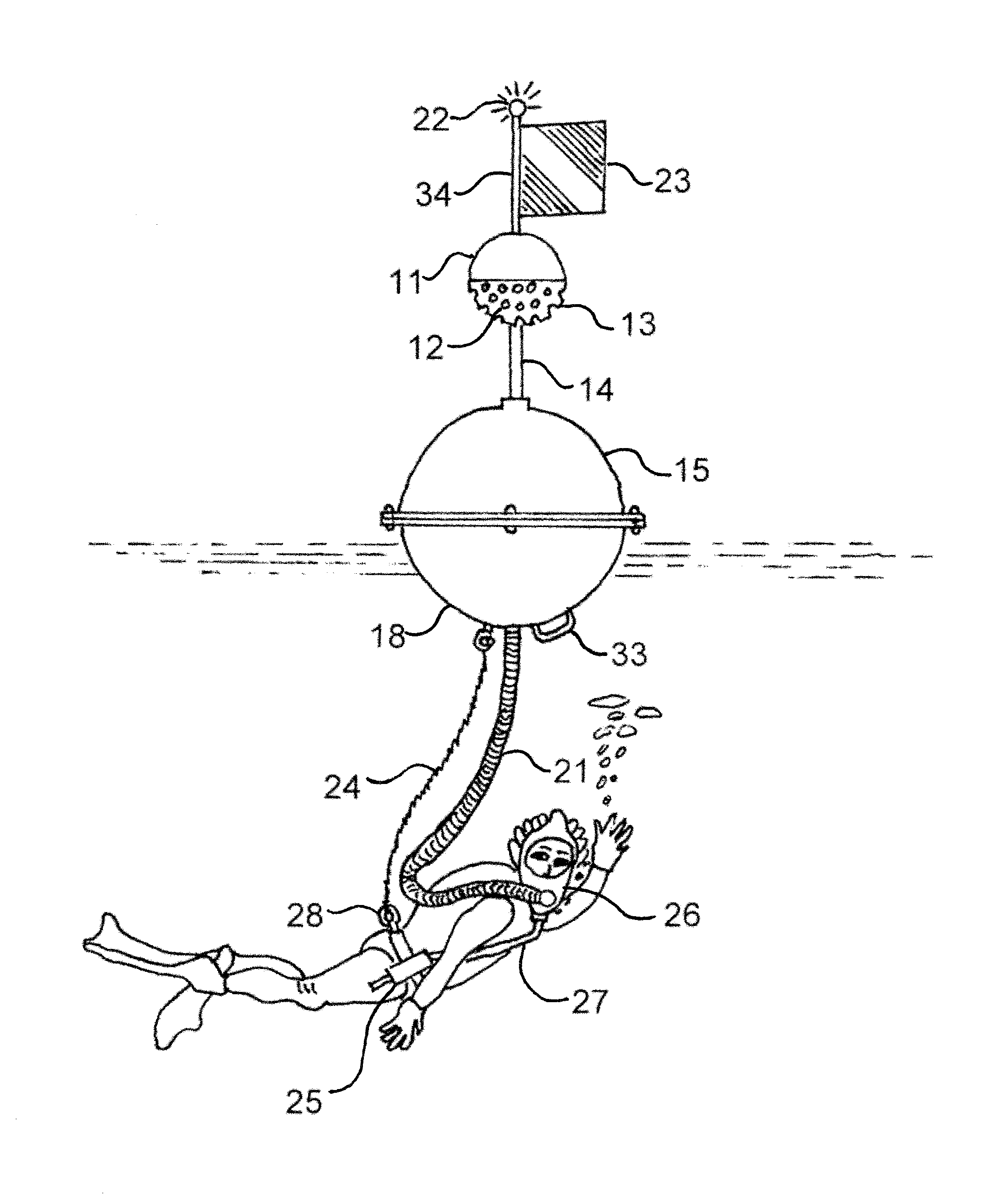
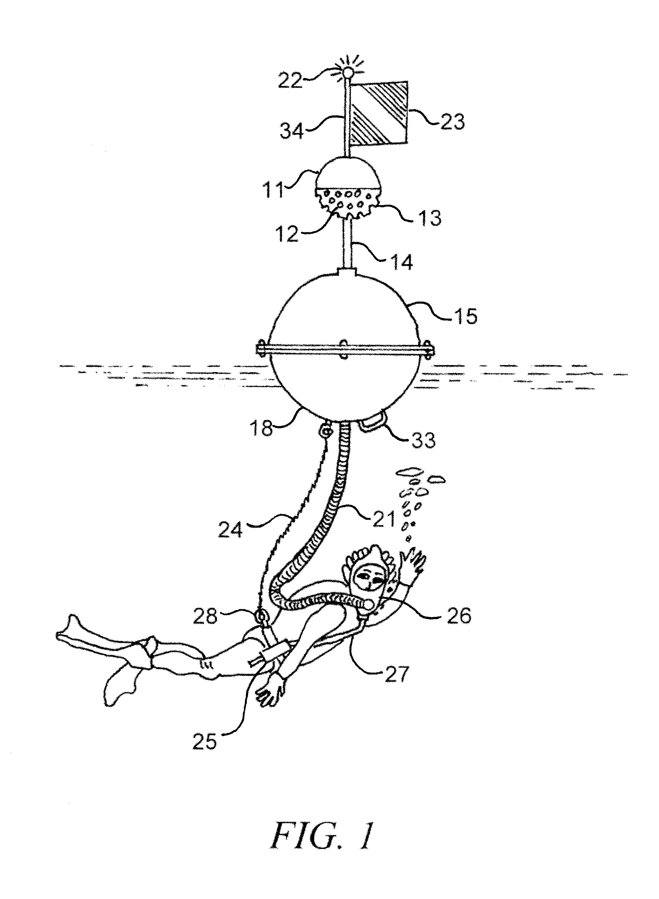
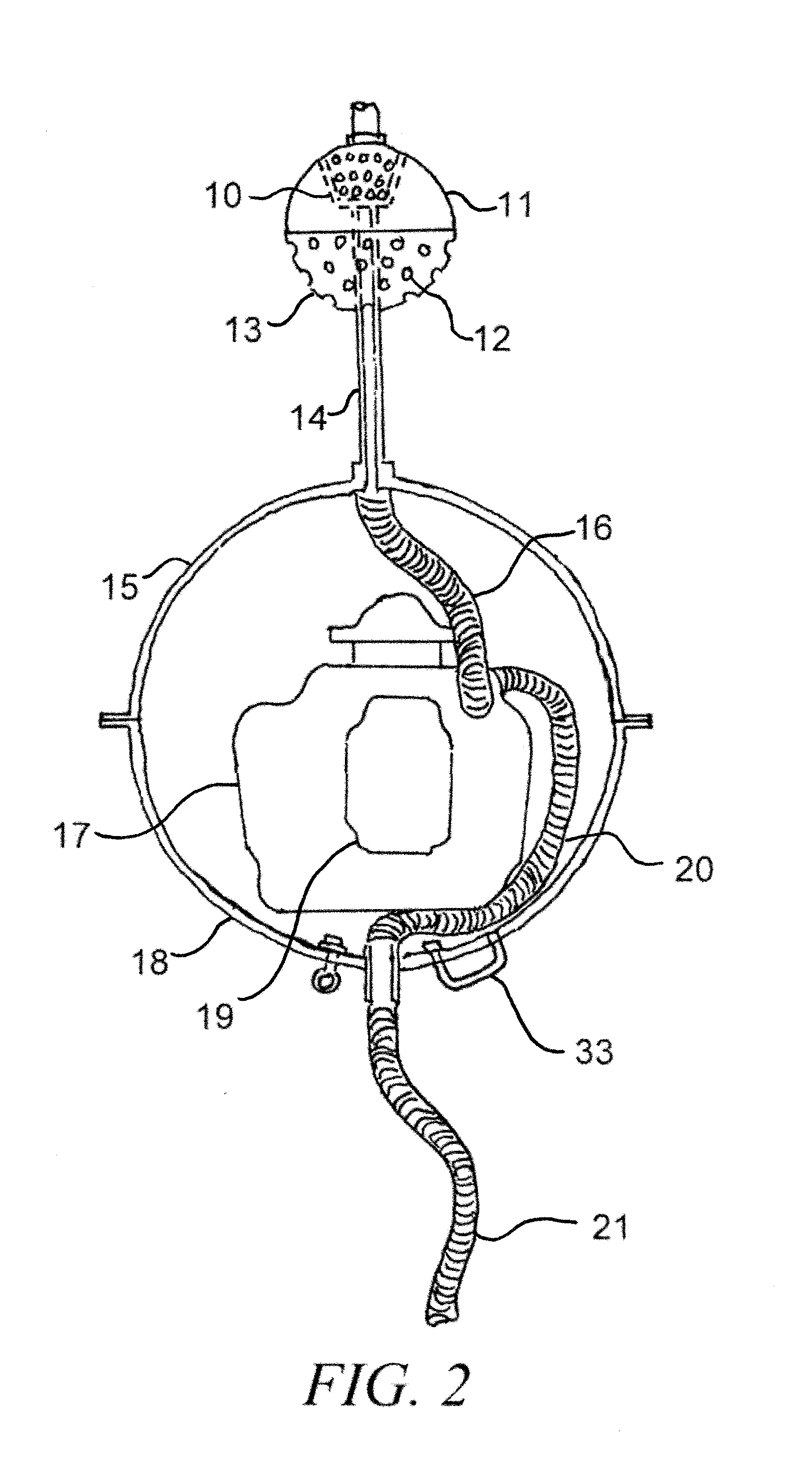
[0022]With reference to FIG. 1 thereof, herein shall be described a new underwater breathing apparatus embodying the principles and concepts of the present invention and generally designated by the reference numeral 1. More specifically it will be noted that FIG. 1 comprises a sealed, hollow buoyant sphere in two parts, the bottom half 18 and the top half 15. The top half 15 is removable to access the inside of the sphere. Both parts 15 and 18 are connected and sealed during normal use. The buoyant sphere supports and is connected to an air intake pipe 14. Mounted on the air intake pipe 14 is a two part air intake sphere. The air intake sphere bottom 13 is attached to the air intake sphere top 11. The bottom half of the air intake sphere 13 has holes 12 that allow air into the air intake sphere and drain water out of the air intake sphere. Connected to the top of the air intake sphere 11 is a hollow shaft 34. Attached to the hollow shaft 34 is a flag 23. Connected to and mounted on ...


PUM


Abstract

The said invention or apparatus is for users to swim and be totally submerged underwater with an adequate supply of air for extended periods of time. The apparatus is a sealed water resistant enclosure supporting a hollow air intake pipe with and attached hollow air intake sphere mounted on the top. The bottom half of the air intake sphere has many holes to allow air into air intake riser and drain unwanted water out. The apparatus does not require regulators, pressure vessels, diaphragm pumps or compressors, internal combustion engines or external power sources. A low pressure blower and filter assembly with a rechargeable and easily replaceable lithium ion battery are mounted inside the buoyant water resistant enclosure. Air is drawn into the low pressure blower suction and through an air filter delivering constant air flow to the swimmer through an attached flexible air supply hose. The apparatus uses three check valves to constrain air flow supply unidirectional to the swimmer while venting excess air. The apparatus has a hand pump to vacate unwanted water from the mouth piece or mask and draw in purging air while the swimmer is submerged. For stability the apparatus has a designed center of gravity below the meta center of the underwater portion of the buoyant water resistant enclosure giving a positive GM and strong self-righting moment in calm or rough seas. For safety the apparatus has a grab handle and a tether line connection from the bottom of the buoyant water resistant enclosure. The tether line is attached to the swimmer.

Description

BACKGROUND OF THE INVENTION[0001]1. Field of the Invention[0002]The said invention relates to a water resistant enclosure used to support an underwater breathing apparatus. The apparatus is designed to be used by recreational tourist snorkelers, pool repair and commercial underwater marine surveyors and vessel repair Engineers as well as private boat and pool owners. The apparatus allows a swimmer to breath underwater comfortably at limited depths for extended periods of time.[0003]2. Background and Related Art[0004]There are many inventions that provide air to swimmers allowing play and or work underwater. Standard snorkels will not work effectively for most people at depths below three feet. The body's diaphragm muscle cannot overcome the water pressure at depths to allow for natural aspiration. Many examples of providing a supply of pressure regulated air to a diver or swimmer have been developed. The SCUBA or self contained underwater breathing apparatus was developed in 1952 an...

Claims


Application Information

Patent Timeline
IPC IPC(8): B63C11/20B63C11/18B63C11/14
CPCB63C11/202B63C11/186B63C11/14
Inventor SMITH, SCOTT ANDREW
Owner SMITH SCOTT ANDREW
Learn More