
Device for atmosphere conditioning for testing combustion engines, and associated method and use

a technology for combustion engines and atmosphere conditioning, applied in the field of devices for atmosphere conditioning for testing combustion engines, can solve the problems that the arrangement of elements does not allow suitable simulation of certain conditions, and achieve the effects of reducing energy consumption, reducing energy consumption, and modifying the inflow air temperatur

Active Publication Date: 2016-12-01
UNIV POLITECNICA DE VALENCIA
View PDF2 Cites 10 Cited by
  • Summary
  • Abstract
  • Description
  • Claims
  • Application Information

AI Technical Summary

Benefits of technology

The patent describes a device that allows for independent control of the pressure and temperature of air entering an engine for testing purposes. This is achieved by using a heat regenerator to transfer heat from the engine's exhaust gases to the air in the engine's inflow conduit. The device can also be used to modify the air temperature with minimal energy expenditure. The technical effect achieved is the ability to precisely control the air temperature and pressure for testing and performance optimization without excessive energy consumption.

Problems solved by technology

In many cases the problem raised is to obtain control over pressure so that it is less than atmospheric pressure, i.e., for simulating a high altitude situation.
Nevertheless, this arrangement of elements does not allow suitable simulation of certain conditions, such as high temperature.

Method used


Image

  • Device for atmosphere conditioning for testing combustion engines, and associated method and use
  • Device for atmosphere conditioning for testing combustion engines, and associated method and use
  • Device for atmosphere conditioning for testing combustion engines, and associated method and use

Examples


first embodiment

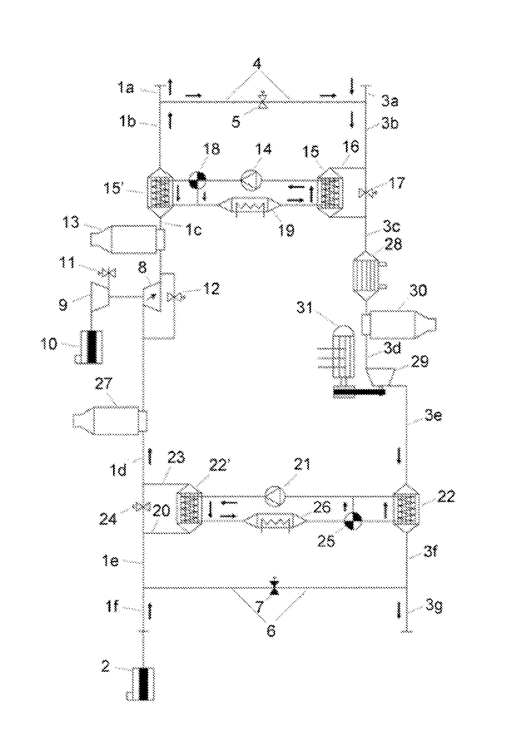
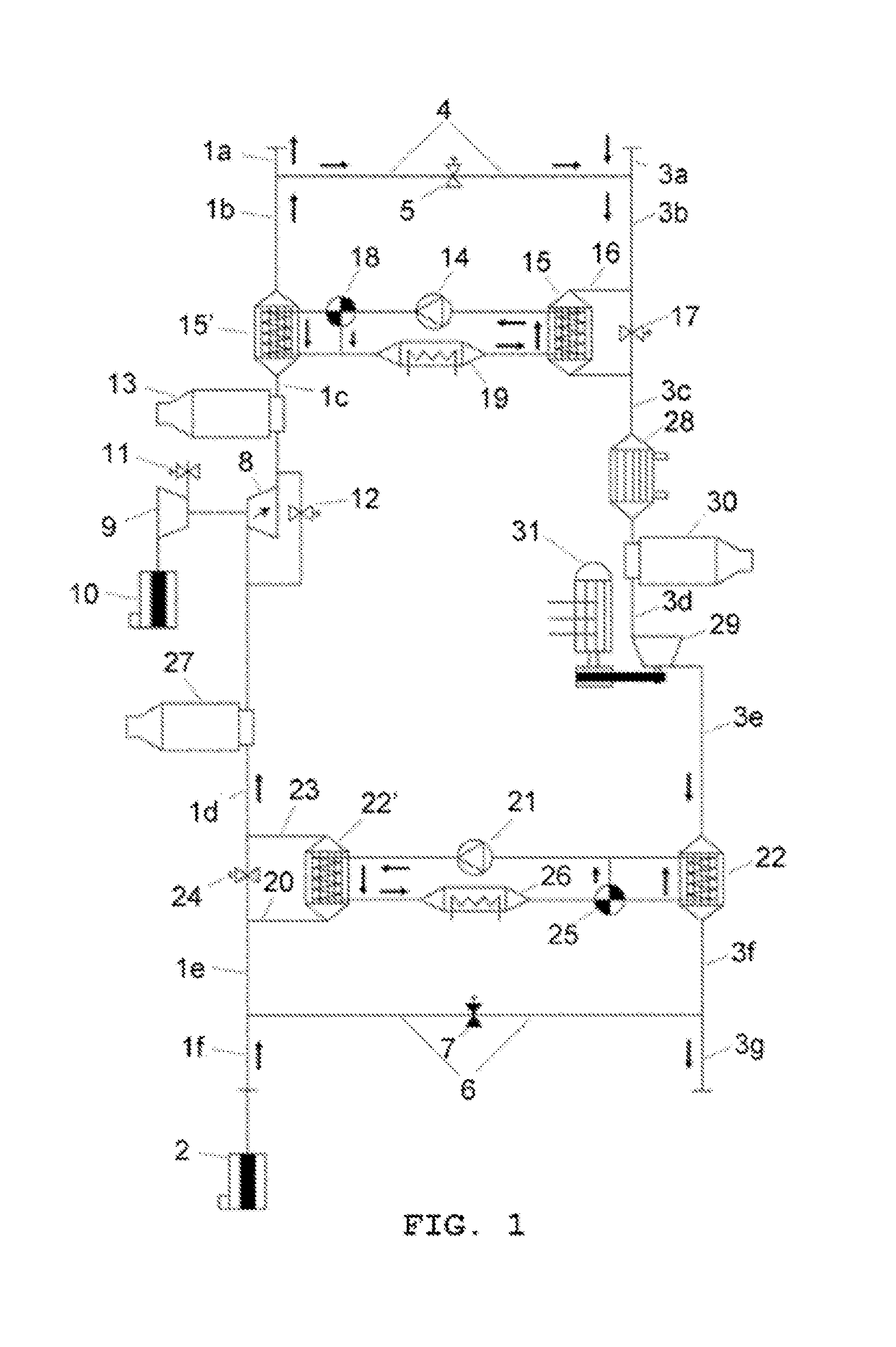
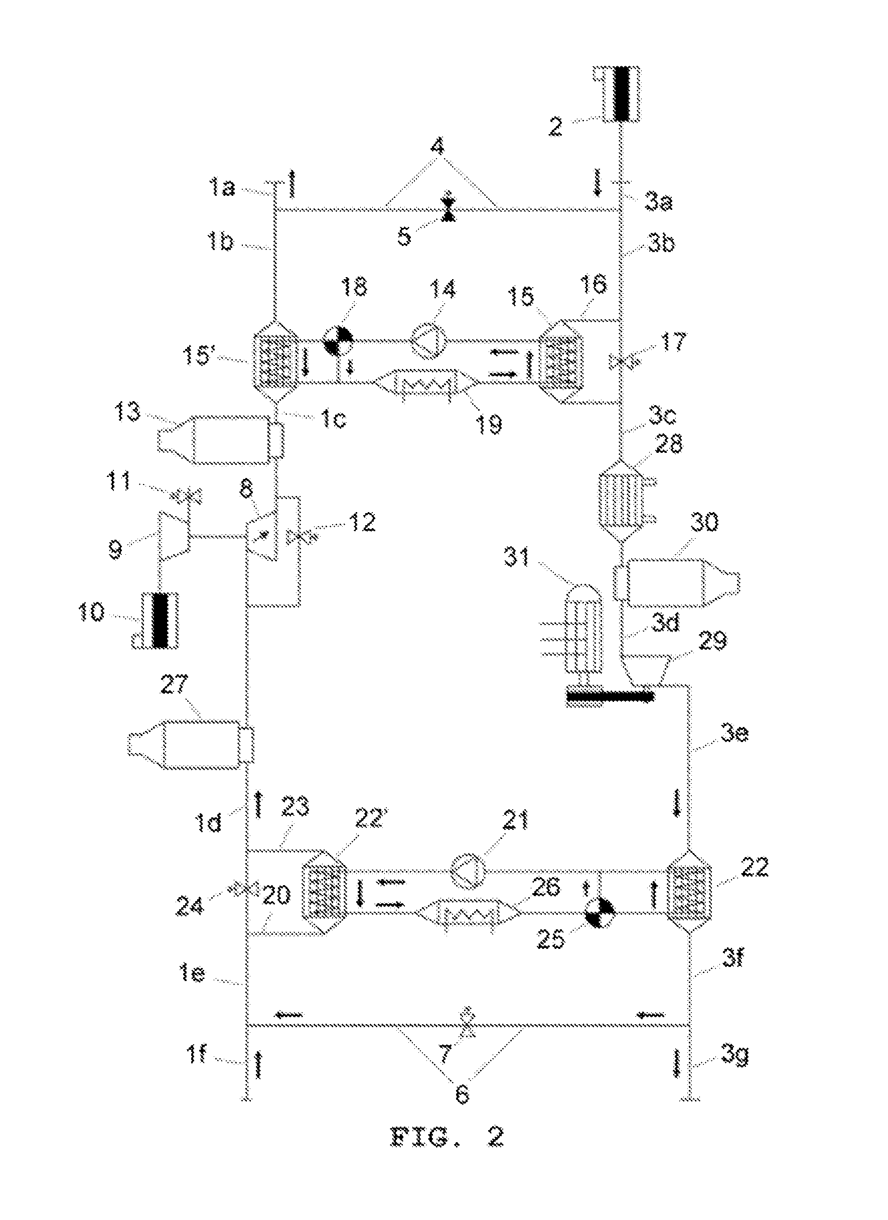
[0066]Therefore, as can be seen based on FIGS. 1 and 2 discussed above, the device according to a first preferred embodiment of the present invention allows simulating atmospheric pressure conditions, both higher and lower, and temperature conditions, both higher and lower, than the atmosphere of the altitude level at which testing is performed. The adjustments that can be made to the pressure and temperature are independent from one another. Furthermore, the increase in the temperature of the inflow air is performed with minimal energy expenditure, since the heat from the exhaust gases of the internal combustion engine which is being subjected to testing is used. A simple change in the configuration of the device of the invention allows easily changing the mode of operation, from simulating higher pressure to simulating lower pressure with respect to the pressure of the surrounding atmosphere.

second embodiment

[0067]Now in reference to FIG. 3, a second preferred embodiment of the device according to the present invention is shown. According to this second embodiment, the device can work with the capacity to simulate lower pressure or higher pressure with respect to the pressure of the surrounding atmosphere without needing to change the respective location of the filter (2) and of the internal combustion engine as was done by changing the mode of operation between the preceding FIGS. 1 and 2.

[0068]The elements in FIG. 3 that are the same as those shown in FIGS. 1 and 2 have the same reference numbers, and will not be described in further detail.

[0069]The device according to the second preferred embodiment of the invention further comprises an assembly of three-way valves that allow the use of the device in a mode for increasing or reducing the inflow air pressure with respect to atmospheric air. Specifically, the device comprises a first three-way valve (32) connecting the inflow conduit ...


PUM


Abstract

The invention relates to an atmosphere conditioning device for testing engines, comprising an inflow conduit connected to an engine admission, an outflow conduit connected to the exhaust of the engine and expelling exhaust gases, a communication conduit which communicates the inflow conduit with the outflow conduit, a supercharging turbogenerator comprising a turbine in the inflow conduit, a bypass valve which diverts the air flow that circulates towards the turbine, a heat regenerator consisting of heat exchangers in the inflow and outflow conduits, connected by the same heat transfer fluid circuit, a bypass valve in the outflow conduit together with the heat exchanger thereof, a heat exchanger in the outflow conduit downstream from the heat regenerator, and a turbocompressor downstream from the heat exchanger.

Description

TECHNICAL FIELD[0001]The present invention generally relates to the field of testing combustion engines, and more specifically to a device for atmosphere conditioning when testing combustion engines.PRIOR ART[0002]Testing and characterizing reciprocating internal combustion engines in test benches require in many circumstances precise pressure and / or temperature control, both in the admission and in the exhaust. This is the case, for example, of testing campaigns intended for calibrating engine control with altitude, cold-starting studies, repeatability of reference conditions in testing campaigns extending over time, etc.[0003]In many cases the problem raised is to obtain control over pressure so that it is less than atmospheric pressure, i.e., for simulating a high altitude situation. This case occurs, for example, when engine operation is to be studied at a level with a higher altitude than that of the laboratory in which testing is performed, or in the case of studying engines a...

Claims


Application Information

Patent Timeline
Patent Type & Authority Applications(United States)
IPC IPC(8): G01M15/02
CPCG01M15/02F02M35/10242
Inventor DESANTES FERN NDEZ, JOSE MARIAGALINDO LUCAS, JOSEPAYRI GONZ LEZ, FRANCISCOPIQUERAS CABRERA, PEDROSERRANO CRUZ, JOSE RAMON
Owner UNIV POLITECNICA DE VALENCIA
Learn More