Self-aligning pipe gripping assembly and method of making and using the same

Active Publication Date: 2016-12-08
NAT OILWELL VARCO LP
View PDF0 Cites 0 Cited by
  • Summary
  • Abstract
  • Description
  • Claims
  • Application Information

AI Technical Summary

Benefits of technology

The patent describes self-aligning pistons and pipe gripping assemblies that can selectively engage and disengage a pipe segment. These assemblies include a cam and roller assembly with a piston body and plurality of rollers that can roll along the cam's surface to align or misalign with the pipe segment. The piston body can slide along a splined shaft between an engaged position and a disengaged position. The self-aligning pistons have a resilient energy-storing member that can bias the rollers into the wells to return the piston to the aligned position. The cam can engage the splined shaft to prevent rotation. The pipe gripping assemblies can create a fluid-tight seal around the self-aligning piston and use hydraulic fluid to actuate the piston. The technical effects of these assemblies include improved alignment accuracy and efficient engagement and disengagement of pipe segments.

Problems solved by technology

When such conventional gripping devices are subject to a large off-center force during operation, however, the conventional gripping device may become damaged, which is both costly and time consuming as the drilling operation must cease in order to repair the damaged pipe gripping device.

Method used


Image

  • Self-aligning pipe gripping assembly and method of making and using the same
  • Self-aligning pipe gripping assembly and method of making and using the same
  • Self-aligning pipe gripping assembly and method of making and using the same

Examples


Embodiment Construction

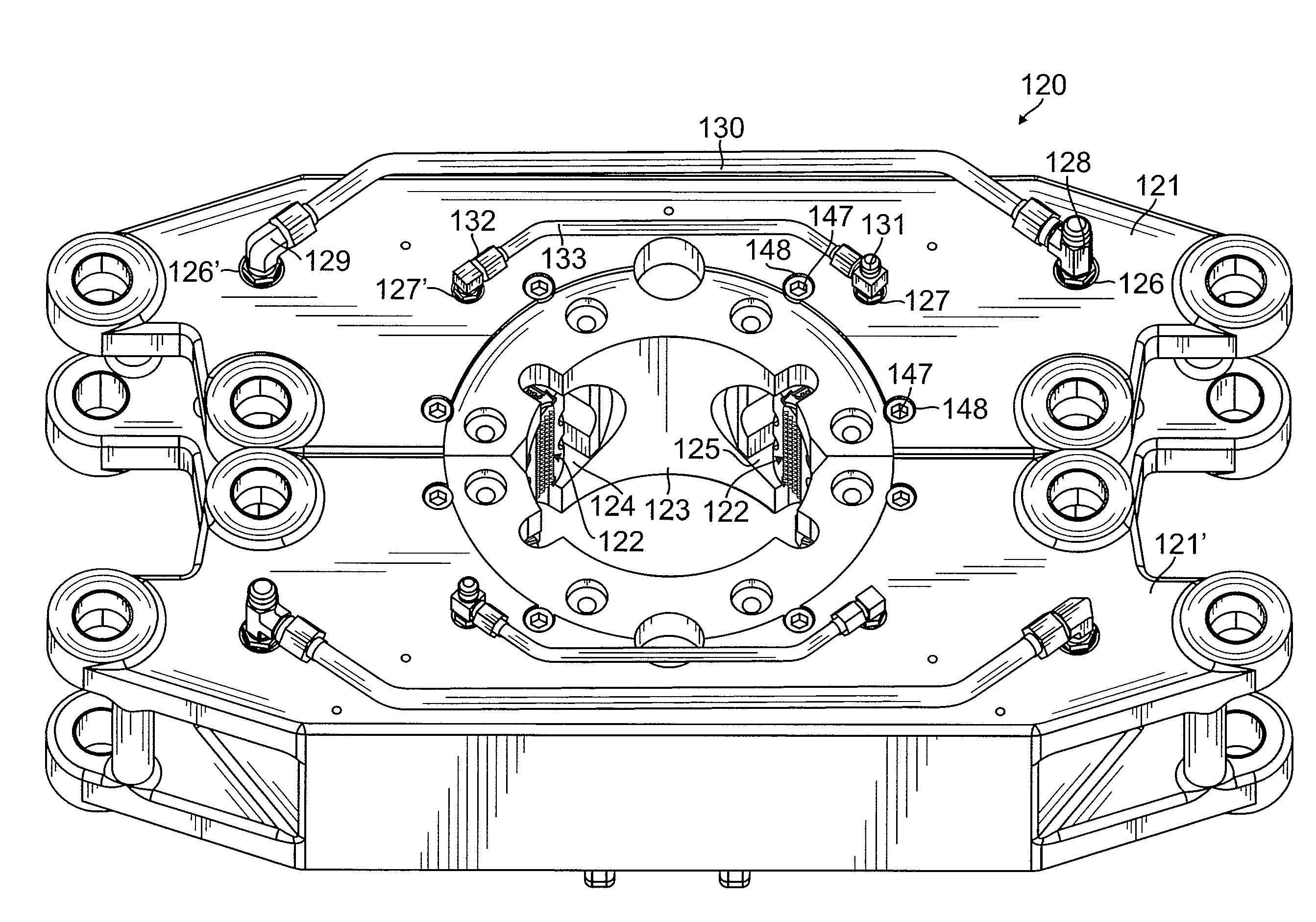
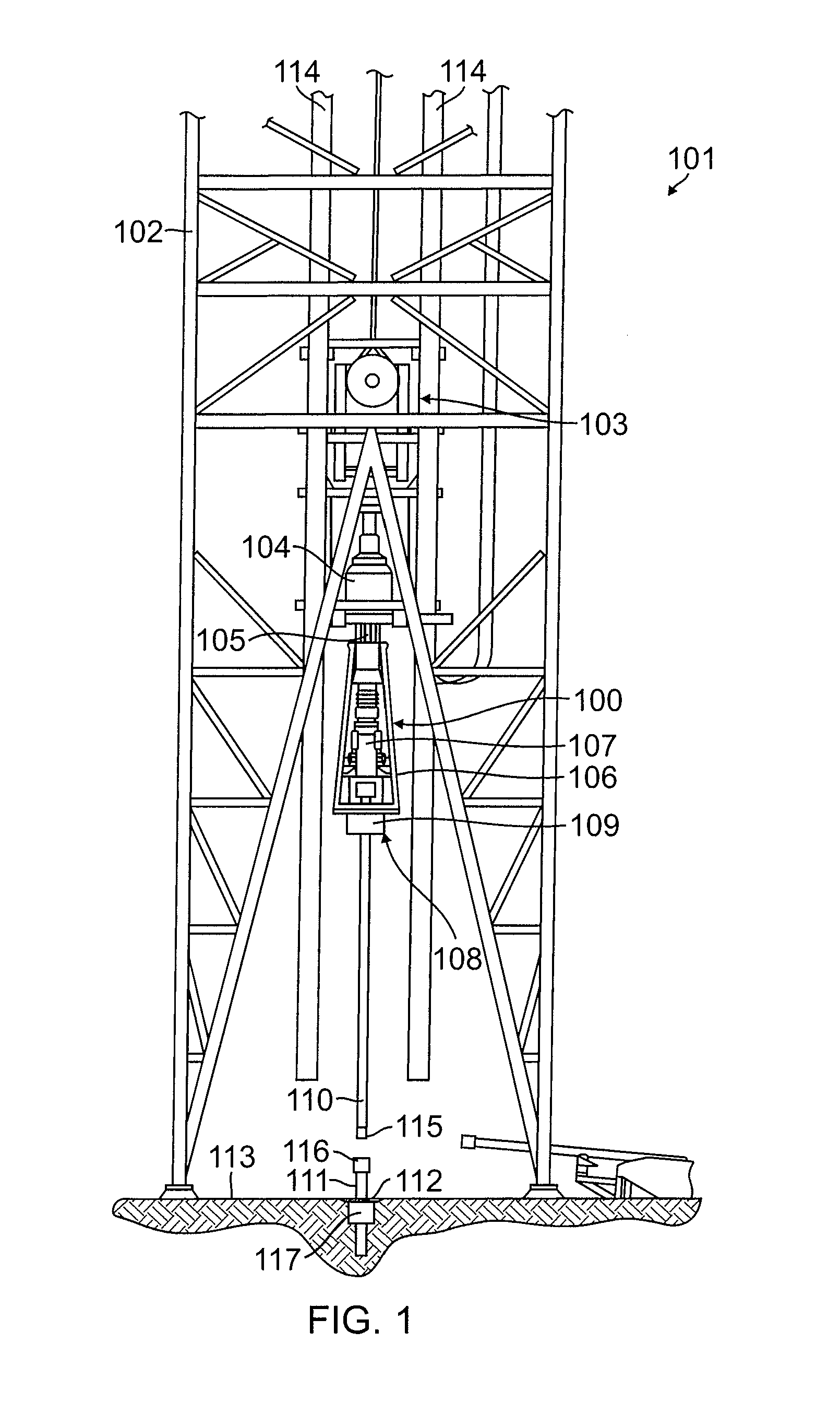
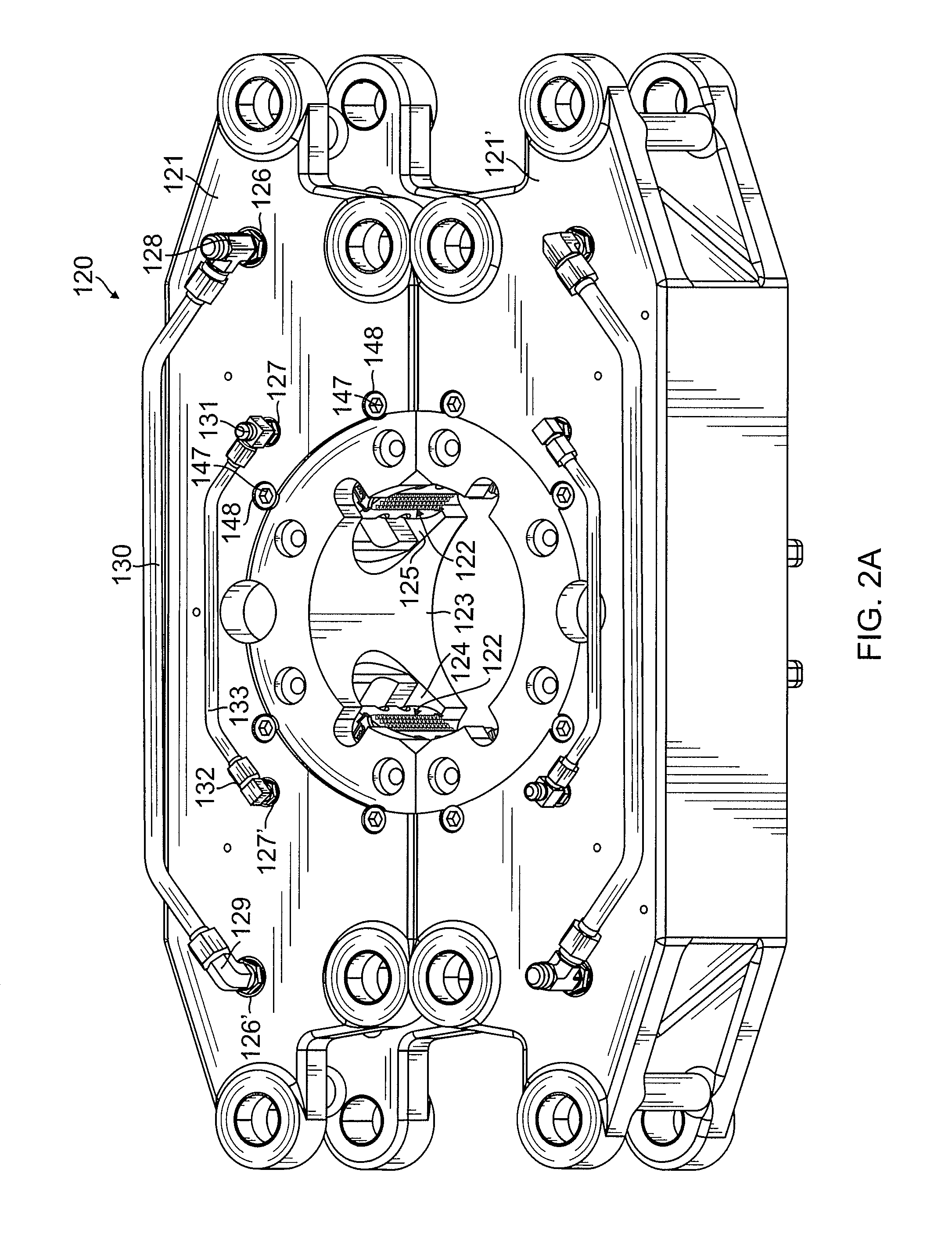
[0040]The present disclosure is directed to pipe gripping assemblies and self-aligning piston assemblies for use in oil well drilling systems to connect and disconnect pipe segments to a pipe string extending downwardly into a well bore. As used herein, the term “pipe segment” refers to casing segments and / or drill segments, and the term “pipe string” refers to casing strings and / or drill strings. The self-aligning piston assemblies of the present disclosure are configured to engage a pipe segment such that an output shaft of an existing top drive may be threaded onto the pipe segment. (i.e., the self-aligning piston assemblies fix the pipe segment such that the output shaft of the top drive may rotate relative to the pipe segment to connect the output shaft to the pipe segment).

[0041]Additionally, in response to an off-center load, the self-aligning piston assemblies of the present disclosure are configured to rotate out of alignment with the pipe segment in order to mitigate stres...


PUM


Abstract

A pipe gripping assembly to selectively engage and disengage a pipe segment includes first and second jaws configured to clamp together around the pipe segment, at least one splined shaft fixedly housed in each of the first and second jaws; and at least one self-aligning piston housed in each of the first and second jaws and configured to slide and to rotate along the splined shaft. The self-aligning pistons each include a piston body, a cam, and a roller assembly coupled to the piston body and to the splined shaft. Each one of the roller assembly is configured to rotate relative to one of the cams.

Description

CROSS-REFERENCE TO RELATED APPLICATIONS[0001]This application is a continuation of, and claims priority to, U.S. application Ser. No. 13 / 907,784 filed on May 31, 2013, which is incorporated herein by reference.BACKGROUND[0002]The present disclosure relates generally to pipe gripping assemblies, and more particularly to self-aligning pipe gripping pistons.[0003]The process of drilling an oil well typically involves assembling drill strings and casing strings and inserting the drill strings and casing strings into the ground to form a well bore. The drill strings and casing strings extend downward from an oil drilling rig and into the ground. The drilling strings and the casing strings are rotationally driven into the ground by a top drive motor on the drilling rig. Drill strings typically include a series of drill segments that are threaded together. The lowest drill segment (i.e., the drill segment extending the furthest into the ground) includes a drill bit at its lower end. Typica...

Claims


Application Information

Patent Timeline
IPC IPC(8): B25J15/00E21B19/16E21B19/06
CPCB25J15/0028E21B19/16E21B19/06E21B17/02E21B17/04
Inventor FOX, PRESTON R.WEST, NEIL E.WELLS, LAWRENCE E.
Owner NAT OILWELL VARCO LP
Why Eureka
Try Eureka