
Cylinder For Opposed-Piston Engines

a technology of opposed pistons and cylinders, which is applied in the direction of machines/engines, positive displacement engines, mechanical devices, etc., can solve the problems of reducing the strength of the cylinder, reducing the efficiency of the cylinder, and reducing the so as to reduce the cost and complexity of the cooling network, and eliminate the need for time-consuming machining. , the effect of easy manufacturing

Active Publication Date: 2016-12-08
ACHATES POWERS INC
View PDF5 Cites 7 Cited by
  • Summary
  • Abstract
  • Description
  • Claims
  • Application Information

AI Technical Summary

Benefits of technology

The peg construction allows for a single direction of coolant flow on the liner's surface, which reduces the complexity of the coolant network and eliminates expensive and time-consuming machining. This cooling system provides mechanical reinforcement and effective cooling in the most intense heat-generating area of the cylinder. The grid of pegs is easy to manufacture and works well for opposed-piston engines.

Problems solved by technology

This intermediate portion bears the highest levels of combustion temperature and pressure that occur during engine operation, and the presence of openings for devices such as fuel injectors, valves, and / or sensors in the intermediate portion diminish its strength and make it vulnerable to cracking, particularly through the fuel and valve openings.
However, while effective at cooling, the impingement construction also creates challenges.
The coolant return branches converge at some point beyond the liner, which makes for complicated coolant routing and, typically, complex cores in the cylinder block.
Another objection to the impingement construction is that it places a premium on the engine space around the cylinder, particularly in the intermediate portion of the liner where room must be found for coolant jets, fuel injectors, valves, and, possibly, sensors.
In addition, due to the compression sleeve, the intermediate portion typically has the largest diameter of the cylinder, which leads to competition for engine space among neighboring cylinders.
The competition can compromise the coolant core shape and / or the coolant flow balance from jet to jet.
Moreover, the impingement cooling construction is complicated and expensive to manufacture.

Method used


Image

  • Cylinder For Opposed-Piston Engines
  • Cylinder For Opposed-Piston Engines
  • Cylinder For Opposed-Piston Engines

Examples


Embodiment Construction

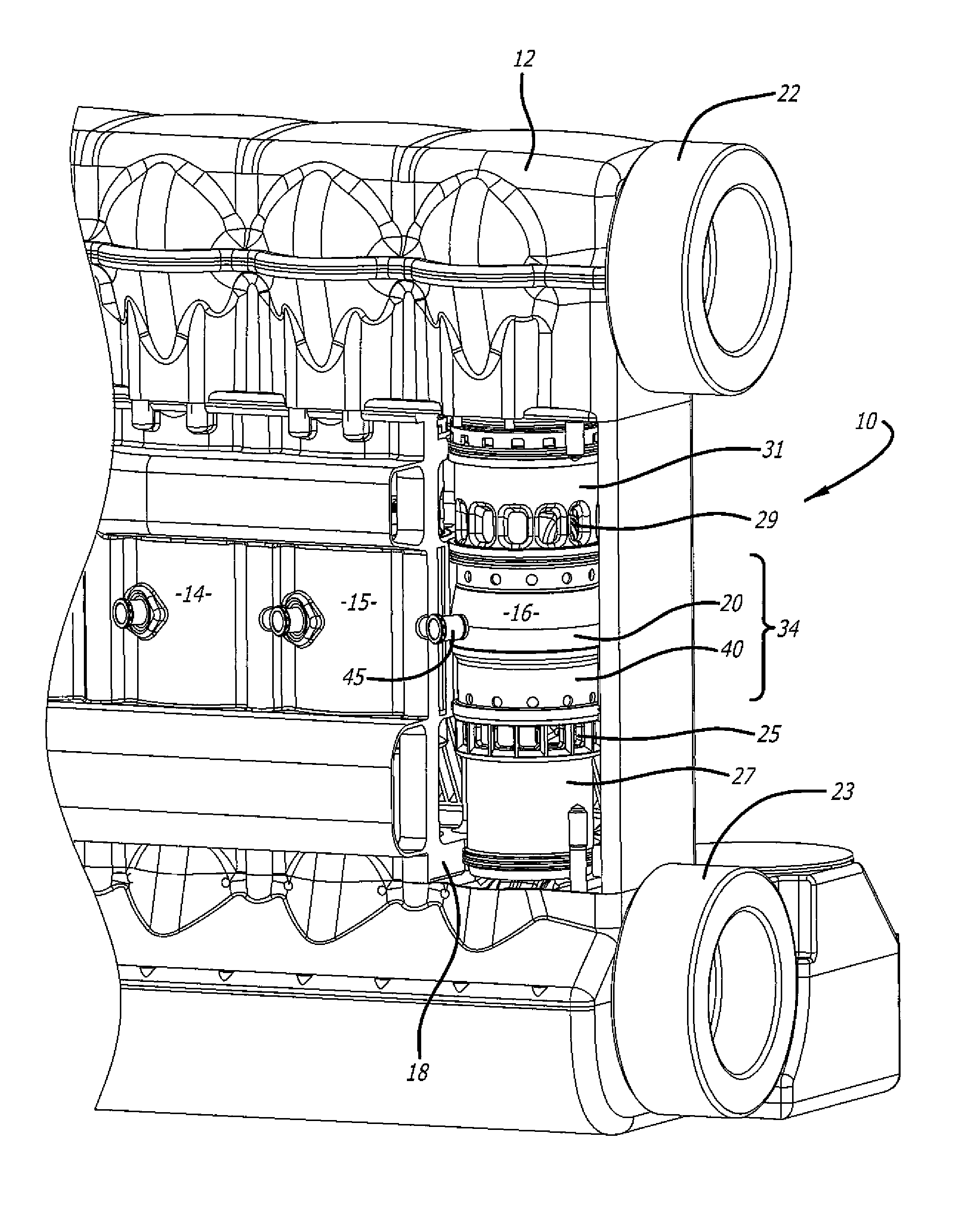
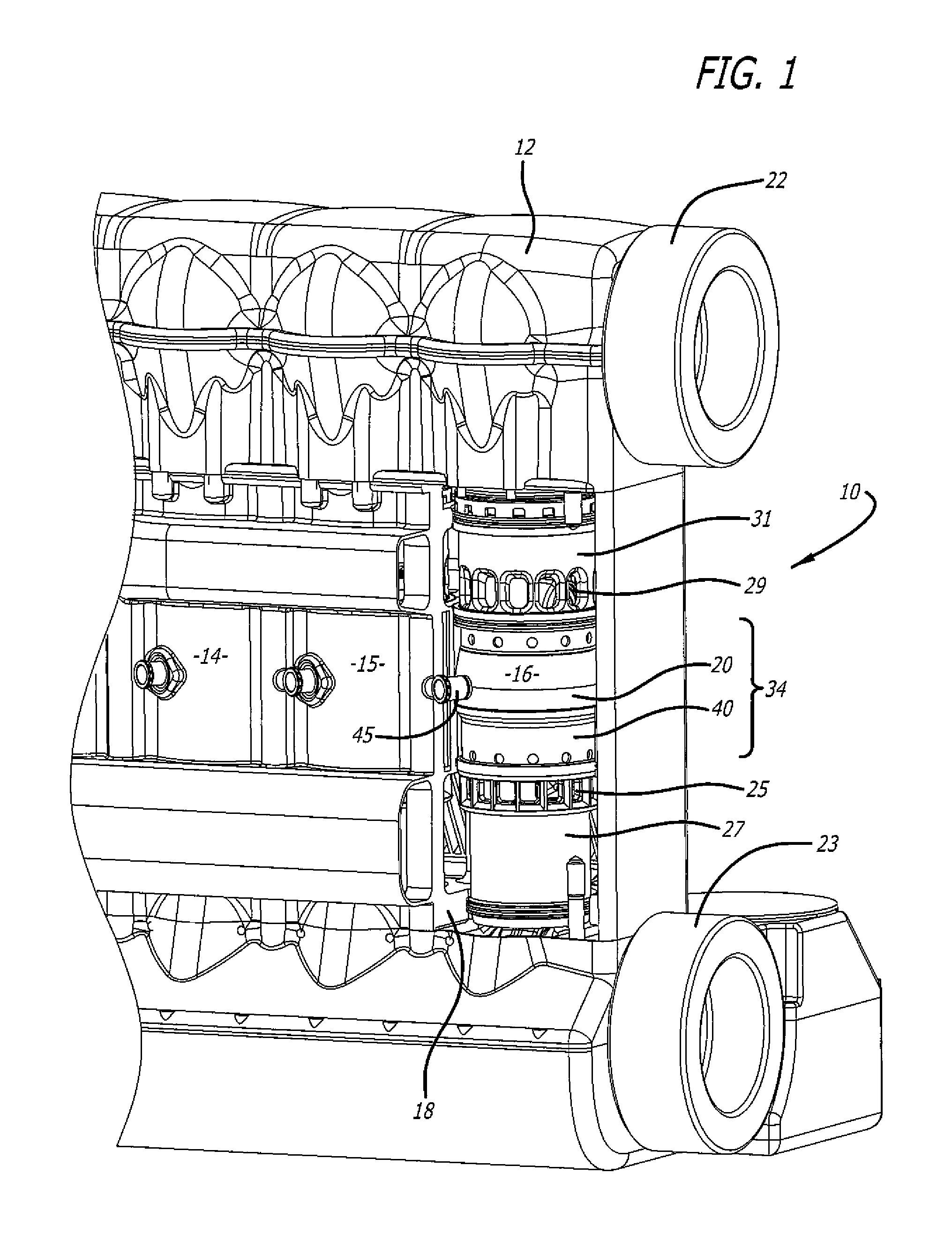
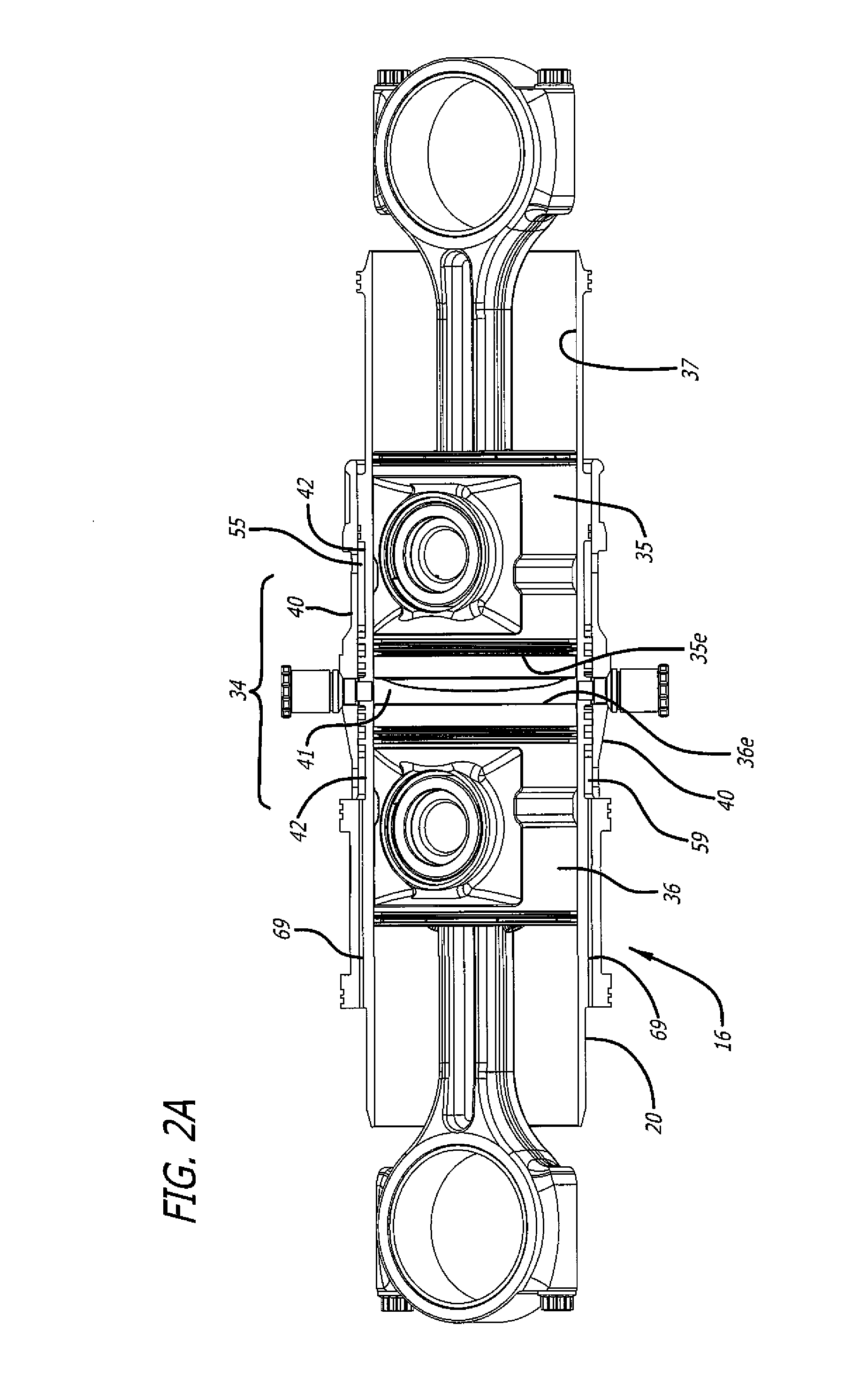
[0016]The figures illustrate a cylinder structure for opposed-piston engines that includes a liner with a bore and longitudinally displaced intake and exhaust ports near respective ends thereof. FIG. 1 shows an opposed-piston engine 10 with a cylinder block 12 with three identically-constructed cylinders 14, 15, and 16. A portion of the cylinder block 12 is removed to show the construction of the cylinder 16 which includes a cylinder tunnel 18 formed in the block in which a cylinder liner 20 is supported. The engine 10 includes two crankshafts 22 and 23. The cylinder liner 20 includes an intake port 25 near a first liner end 27, exhaust port 29 near a second liner end 31, and an intermediate portion 34 situated between the intake and exhaust ports. As per FIG. 2A, a pair of pistons 35 and 36 are disposed in the bore 37 of the liner with their end surfaces 35e and 36e in opposition. As per FIGS. 1 and 3, compression sleeve 40 is received over the liner 20. A fuel injector 45 is suppo...


PUM


Abstract

A cylinder for opposed-piston engines includes a liner with a bore and longitudinally displaced intake and exhaust ports near respective ends thereof. An intermediate portion of the liner between the exhaust and intake ports contains a combustion chamber formed when the end surfaces of a pair of pistons disposed in opposition in the bore are in close mutual proximity. A compression sleeve encircles and reinforces the intermediate portion of the liner. An annular grid of pegs disposed between the intermediate portion and the compression sleeve supports the compression sleeve against the liner and defines a turbulent liquid flow path extending across the intermediate portion in a direction that parallels the longitudinal axis of the liner.

Description

RELATED APPLICATIONS[0001]This Application contains subject matter related to the subject matter of commonly-owned U.S. application Ser. No. 13 / 136,402, filed Jul. 29, 2011 for “Impingement Cooling of Cylinders of Opposed-Piston Engines”, published as US 2013 / 0025548 A1 on Jul. 31, 2013, now U.S. Pat. No. 8,485,147, issued on Jul. 16, 2013; commonly-owned U.S. application Ser. No. 13 / 942,515, filed Jul. 15, 2013 for “Impingement Cooling of Cylinders of Opposed-Piston Engines”, published as US 2013 / 0298853 A1 on Nov. 14, 2013; and commonly-owned U.S. application Ser. No. 14 / 255,756, filed Apr. 17, 2014 for “Liner Component for a Cylinder of an Opposed-Piston Engines”.FIELD OF THE DISCLOSURE[0002]The field relates to the structure of a cylinder for opposed-piston engines. More specifically the field is directed to strengthening and cooling cylinder liners for such engines.BACKGROUND OF THE DISCLOSURE[0003]The cylinder of an opposed-piston engine is constituted of a liner (sometimes ca...

Claims


Application Information

Patent Timeline
IPC IPC(8): F02F1/14F02F1/00
CPCF02F1/004F02F1/14F01B7/14F02B25/08F02B75/28F02F1/10F02F1/102F02F1/186F01P2003/021
Inventor FUQUA, KEVIN B.
Owner ACHATES POWERS INC
Learn More