Interferometric sensor

a sensor and interferometer technology, applied in the field of interferometer sensors, can solve the problems of difficult to distinguish voltage or current drift from other effects, fundamental limit to the achievable measurement range, and periodwise ambiguity, so as to increase the unambiguous measurement range of an interferometer sensor. the effect of removing period ambiguity

Active Publication Date: 2016-12-08
HITACHI ENERGY SWITZERLAND AG
View PDF4 Cites 7 Cited by
  • Summary
  • Abstract
  • Description
  • Claims
  • Application Information

AI Technical Summary

Benefits of technology

[0026]A further aspect of the invention relates to a method determining a first measure representative of the principal value of the relative phase shift and determining a second measure representative of the cross-correlation between two waves, both measures derived from an interference signal of the two waves passing through a sensing element introducing the relative phase shift between the two waves by interaction with the measurand, and converting the first and second measures to a measurand value. The combined measurements of the cross-correlation measure and the principal value of the relative phase shift can be advantageously used to remove period ambiguity from the phase shift measurement and hence can largely increase the unambiguous measurement range of an interferometric sensor.

Problems solved by technology

[2], the periodwise ambiguity (between φ and φ+2nπ) is an inherent problem for all interferometric measurements.
However, for absolute measurements in which history information is either unavailable or unreliable, the periodwise ambiguity is a genuine problem and places a fundamental limit to the achievable measurement range.
Furthermore, the latter makes it difficult to distinguish voltage or current drifts from other effects such as changing optical loss, stress-induced birefringence, etc.
[5], to address the drift problem by chopping the applied voltage, but such solutions are not readily adaptable to HV applications.
The periodwise ambiguity remains a limitation in this technique, and therefore the sensor as described is also only capable of measuring a DC electro-optic phase shift (1) between −π and +π.
The two-wavelength (or multi-wave-length) method, however, requires at least two sets of light sources and detectors at distinct wavelengths, which significantly add to the complexity and may reduce the reliability of the sensor system.
However, no phase measurement is performed in this technique, and scanning through multiple interference fringes is required to measure the contrast.

Method used


Image

  • Interferometric sensor
  • Interferometric sensor
  • Interferometric sensor

Examples


Embodiment Construction

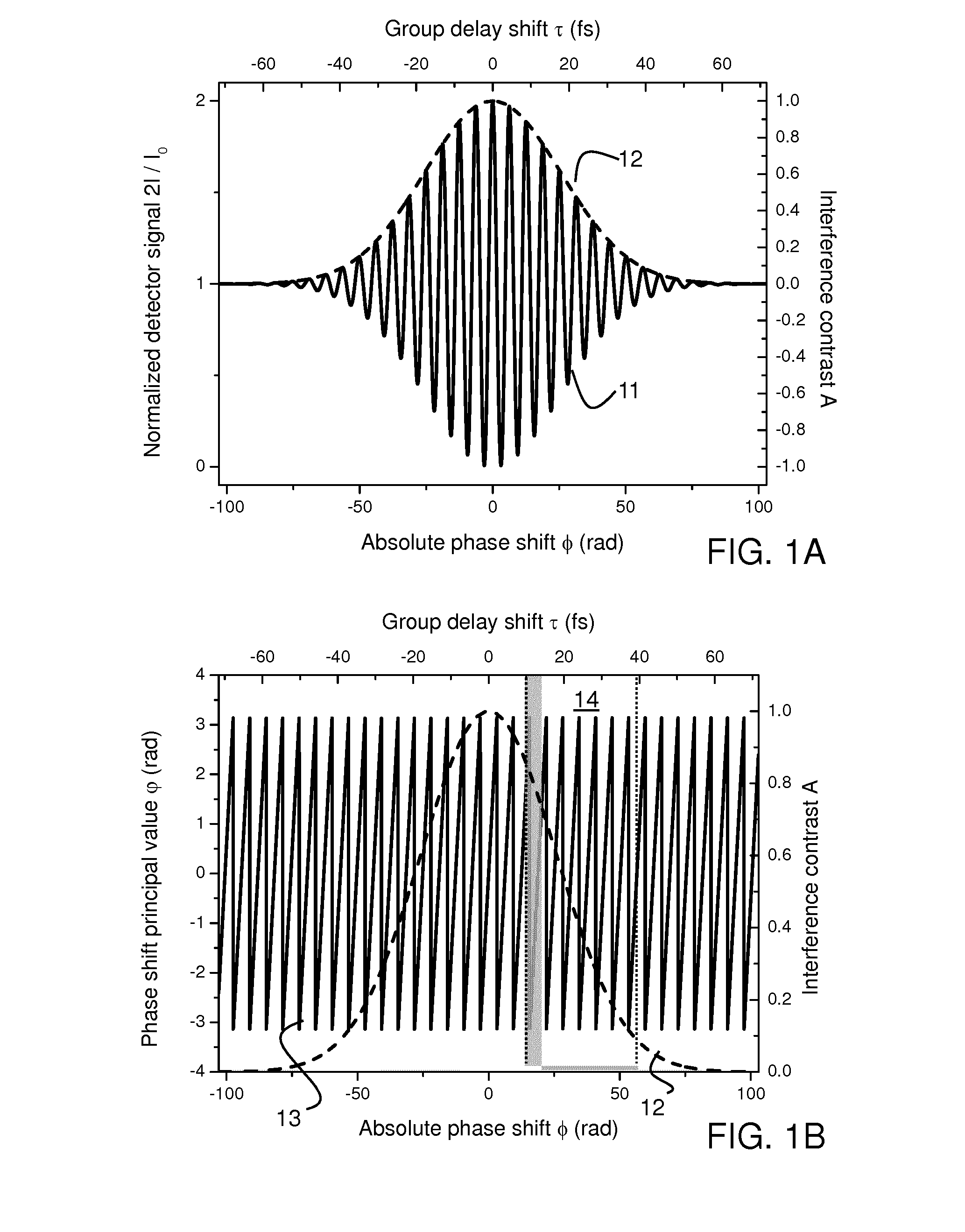
[0036]In the following, the example of an orthogonal-polarization interferometer is used to describe steps of signal handling or processing used in the present invention. It should be noted that the underlying principles of the example described apply to many different types of interferometric sensors otherwise suffering from period-wise ambiguity. Hence they can actually be applied to any types of interferometers (Michelson, Mach-Zehnder, Fabry-Perot, Sagnac, etc.), with only minor differences in implementation or interpretation. Typically, in an interferometer the optical detector signal after the interference can be written as the sum of a base term, which is proportional to the output power of the light source, and a sinusoidal term which varies with the phase shift φ between the interfering waves as influenced by the measurand. In addition, the interference of non-monochromatic waves introduces a further modification Aτ to the detector signal which is related to the temporal co...


PUM


Abstract

An interferometric sensor and related methods are provided, with a sensing element whereby a measurand induces a relative phase shift between two waves, at least one detector measuring an interference signal between the two waves, and further including a phase shift detection unit having as input the interference signal and determining a first measure representative of the principal value of the relative phase shift, and a contrast detection unit having as input the interference signal for determining a second measure representative of the cross-correlation between the two waves, and a further a processing unit for converting the first and second measures to a measurand value.

Description

FIELD OF THE INVENTION[0001]The invention relates to an interferometric sensor, wherein a change in the parameter to be measured is related to a relative phase shift between two waves, such as an electro-optic voltage sensor, particularly for DC electrical voltages, or a fiber-optic current sensor (FOCS).BACKGROUND OF THE INVENTION[0002]Sensors which rely on the interference between two waves, typically two orthogonal polarization modes of a wave, are known and used in a wide range of technical fields. The detector signals of these sensors are related to the cosine of the relative phase shift φ between the two waves. Therefore, phase shifts of φ and ±φ+2nπ (n being an integer number, also referred herein as the period counter) produce the same interference output, and hence cannot be distinguished from one another. Consequently, the unambiguous measurement range of the relative phase shift is limited to a range of [0, π].[0003]For example, an electro-optic DC voltage sensor consisti...

Claims


Application Information

Patent Timeline
Patent Type & Authority Applications(United States)
IPC IPC(8): G01R15/24G01D5/353
CPCG01D5/35306G01R15/241G01D5/266G01D5/353G01D5/35309
Inventor GU, XUNMARCHESE, SERGIO VINCENZOBOHNERT, KLAUSFRANK, ANDREAS
Owner HITACHI ENERGY SWITZERLAND AG
Why Eureka
Try Eureka