Localization method and apparatus

a technology of localization and method, applied in the direction of distance measurement, reradiation, instruments, etc., can solve the problems of large processing power, heavy sensor equipment, and algorithms that are too slow for many applications, and achieve the effect of higher frame ra

Active Publication Date: 2016-12-08
BARROWS GEOFFREY LOUIS +2
View PDF15 Cites 20 Cited by
  • Summary
  • Abstract
  • Description
  • Claims
  • Application Information

AI Technical Summary

Benefits of technology

[0008]In one embodiment, each of the one or more optical receivers of the system comprises a camera system. In another embodiment, for each optical transmission, optics of the camera system are configured so that the majority of a light of the optical transmission is acquired by an associated window of pixels that comprises substantially fewer pixels than a total number of pixels within the camera system, and the one

Problems solved by technology

One challenge in robotics is that of determining the 6 degree of freedom (6-DOF) state of a platform within an environment.
However, they generally require substantial processing power and the use of heavy sensor equipment

Method used


Image

  • Localization method and apparatus
  • Localization method and apparatus
  • Localization method and apparatus

Examples


Embodiment Construction

[0037]Coordinate System for Purposes of Discussion

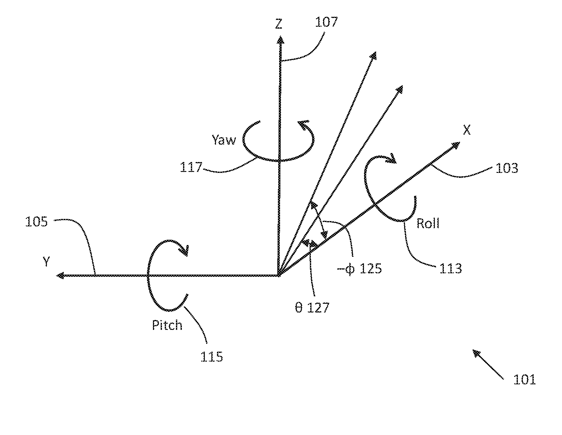
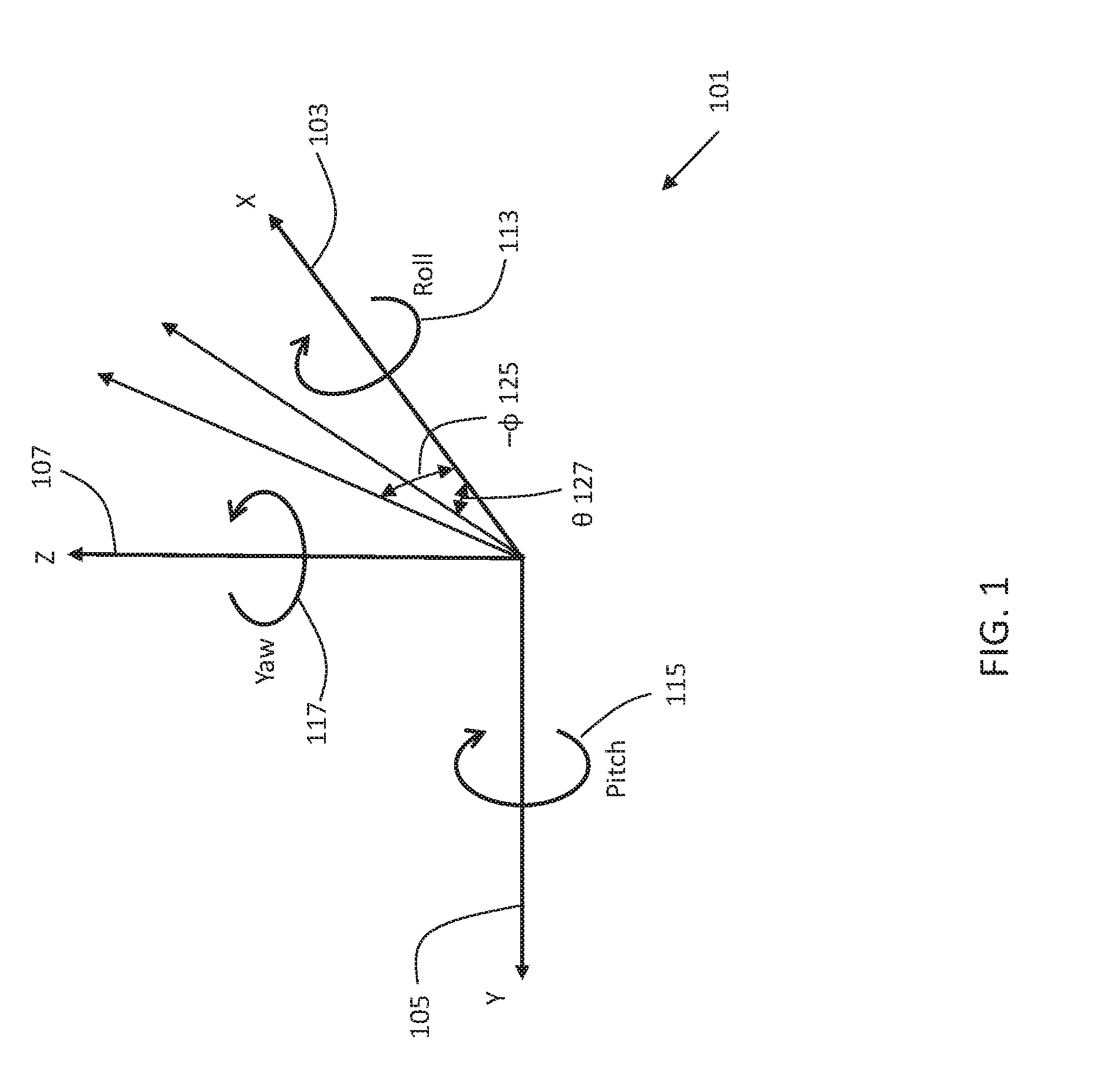
[0038]Refer to FIG. 1 for a depiction of the coordinate system 101 we will use in the teachings below. It shall be understood that the depicted coordinate system 101 is for illustrative purposes and that other coordinate systems may be used, including the use of quaternions for representing pose, and the coordinate system 101 depicted is used for purposes of illustration. We will in general refer to the forward direction 103 as “positive X” and the left-ward direction 105 as “positive Y”. Therefore, following the right-hand rule, the vertical direction upward 107 will be “positive Z”. For pose, we will define rotations around these axes using the right-hand rule. Positive roll 113 is clockwise rotation around the X-axis as shown, and may be referred to with the variable ψ (not shown). Positive yaw 117 is rotation to the left around the Z-axis as shown. A yaw angle e.g. 127 may be referred to with the variable θ. Positive pitch 115 is...


PUM


Abstract

An apparatus for determining the location and state of an object in an environment is disclosed. Three or more light-emitting beacons are located in the environment, and each beacon transmits a light pattern that contains information needed to identify the beacon. An optical receiver is attached to the object whose location needs to be determined. The optical receiver comprising one or more cameras images the beacons, and identifies the apparent direction from which the beacon is coming based on the pixel or pixels illuminated by the beacon. The optical receiver also decodes the light pattern transmitted by each beacon to identify it. Finally, based on knowledge of the locations of the beacons in the environment and based on the apparent directions from which the beacons appear to be coming, the optical receiver determines its location, and thus the location of the object.

Description

CROSS-REFERENCE TO RELATED APPLICATIONS[0001]This application claims the benefit to U.S. Provisional Patent Application No. 62 / 172,104 entitled “Localization Method and Apparatus” by G. Brill et al. and filed Jun. 7, 2015.FIELD OF THE INVENTION[0002]The teachings presented herein relate to the determination of an object's location within an environment.BACKGROUND OF THE INVENTION[0003]One challenge in robotics is that of determining the 6 degree of freedom (6-DOF) state of a platform within an environment. By 6-DOF state, we refer to both the 3-DOF location of a platform in Cartesian X-Y-Z space and the 3-DOF pose. The X-Y-Z location may be computed in reference to an objective frame of reference, which may be fixed as Earth-bound or attached to another frame of reference. The 3-DOF pose may be expressed as Euler angles (roll, pitch, and yaw) or in quaternions. In this document, we shall refer to the act of determining the 6-DOF state of a platform as the process of “localization”.[...

Claims


Application Information

Patent Timeline
IPC IPC(8): G05D1/02H04B10/60G01S17/42G01C1/00G01C21/20G01S17/93H04B10/50G01C3/08
CPCG05D1/0214H04B10/50H04B10/60G01S17/42G01C1/00G01C21/20G01S17/93G01C3/08H04B10/116G01S5/16G05D1/0246
Inventor BARROWS, GEOFFREY LOUISBRILL, GREGORYNEELY, CRAIG WILLIAM
Owner BARROWS GEOFFREY LOUIS
Why Eureka
Try Eureka