
Wireless camera with motion detector and face detector

a technology of face detector and wireless camera, which is applied in the field of wireless camera with motion detector and face detector, can solve the problems of many vulnerabilities in such a system, the inability to send such emails, and the difficulty of installing multiple cameras inside and outside a residence or commercial, so as to improve the security of the dwelling

Inactive Publication Date: 2016-12-08
AUGUST HOME
View PDF11 Cites 33 Cited by
  • Summary
  • Abstract
  • Description
  • Claims
  • Application Information

AI Technical Summary

Benefits of technology

The present invention aims to enhance the security of a home by using a motion detection device to identify individuals approaching the property. In response, the camera is triggered to capture the individual's image. This technology allows for improved security in homes by providing an efficient means to alert security personnel to potential security threats.

Problems solved by technology

Such cabling makes it difficult to install the multiple cameras inside and outside a residence or commercial because of routing of such long cabling between a user accessible box and cameras.
However, there is much vulnerability in such a system.
If internet is not working at the time of intrusion because phone or internet cables are externally cut, then no such email could be send.
One of the disadvantages of such a security system is that if internet access deliberately interrupted at the time of a security event, then it is not possible to stream the data for the event to the remote PC for recording.
Furthermore, such a system requires continuous stream of multiple video streams over local and wide area networks, which places a considerably load on such networks, thus causing unreliable operations and slowing other network activity.
Cabled systems using Ethernet cabling also require difficult cabling of multiple camera units.
Thus, it becomes difficult and unreliable to transfer plurality of live compressed video stream in real-time without interruptions.

Method used


Image

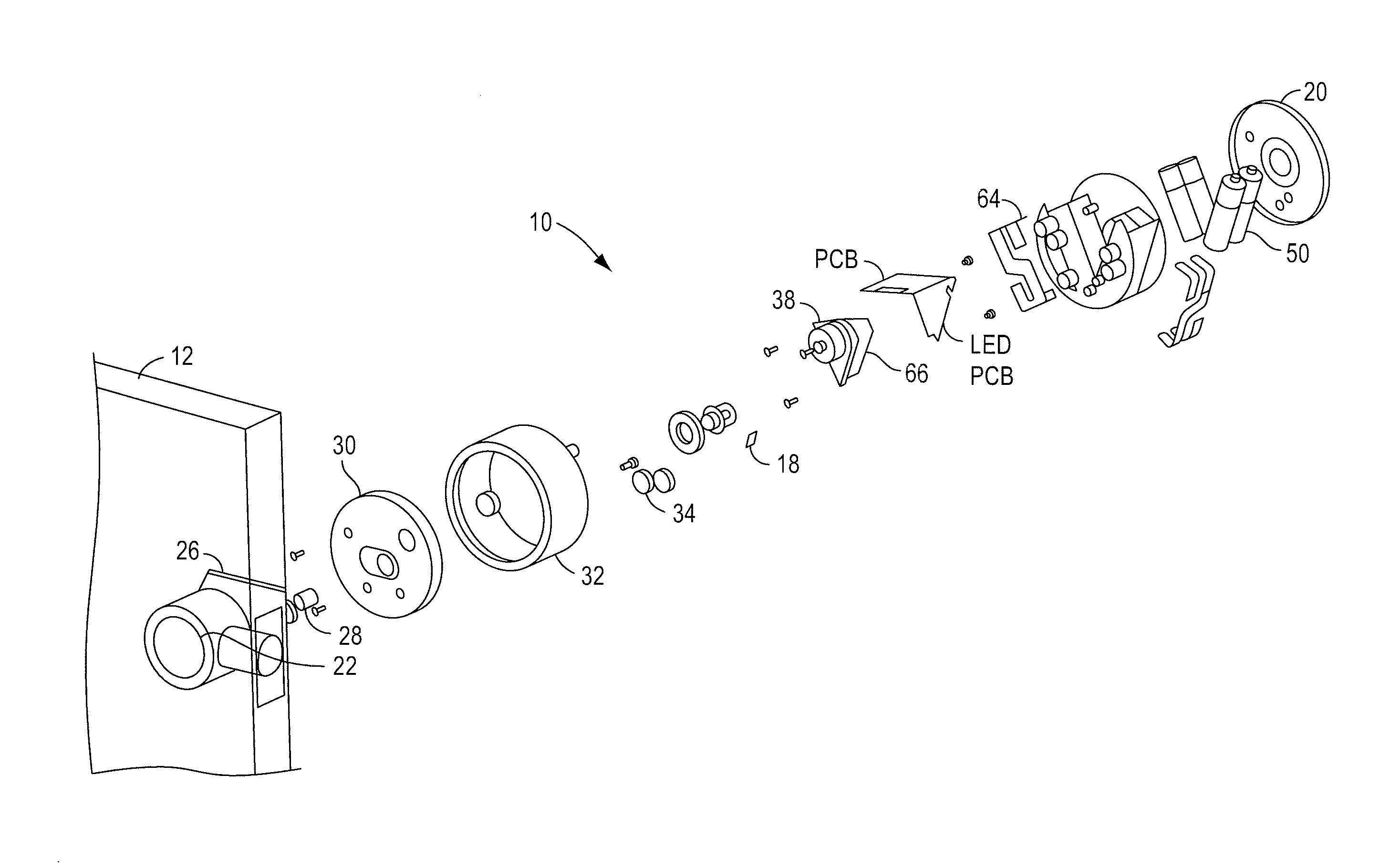
  • Wireless camera with motion detector and face detector
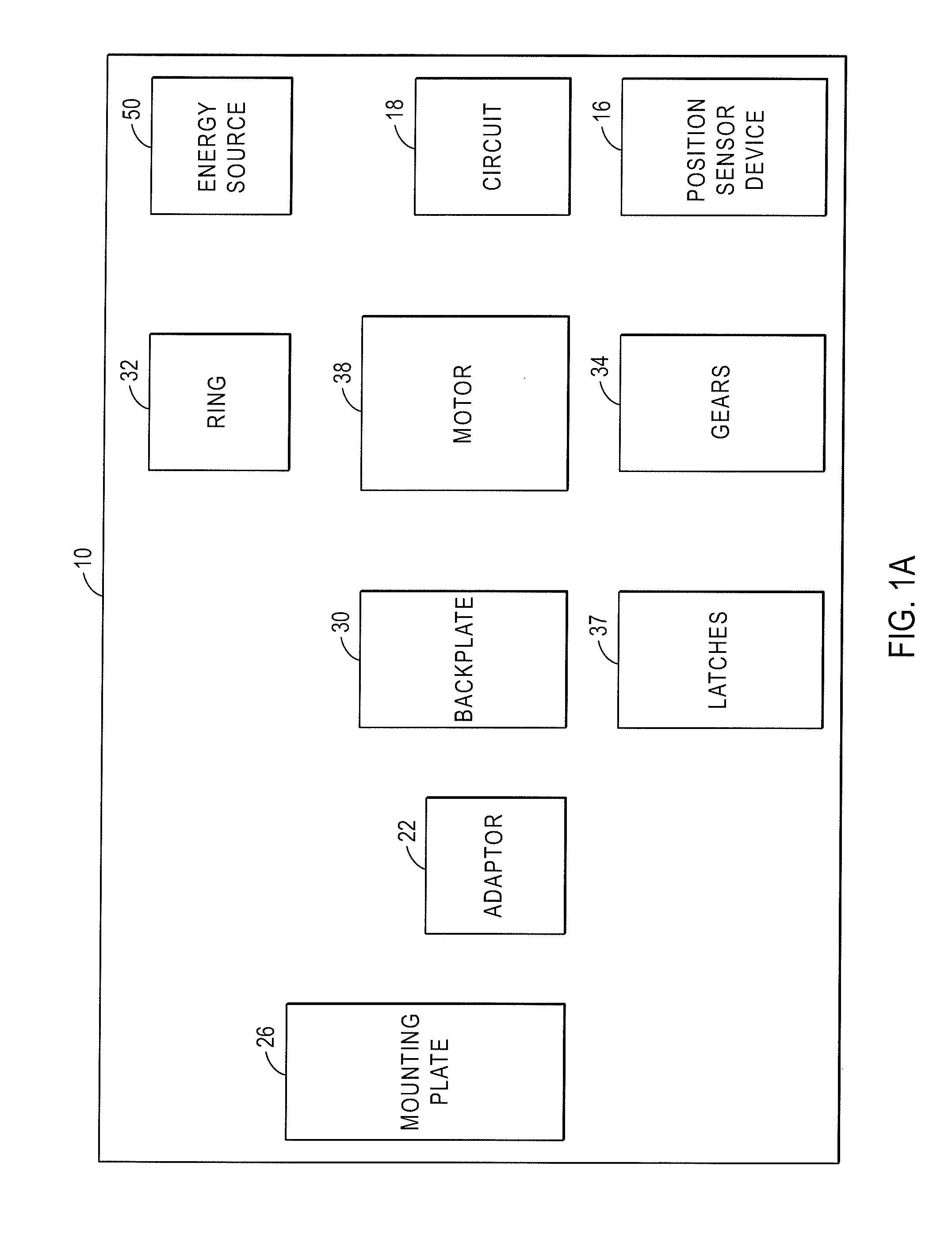
  • Wireless camera with motion detector and face detector
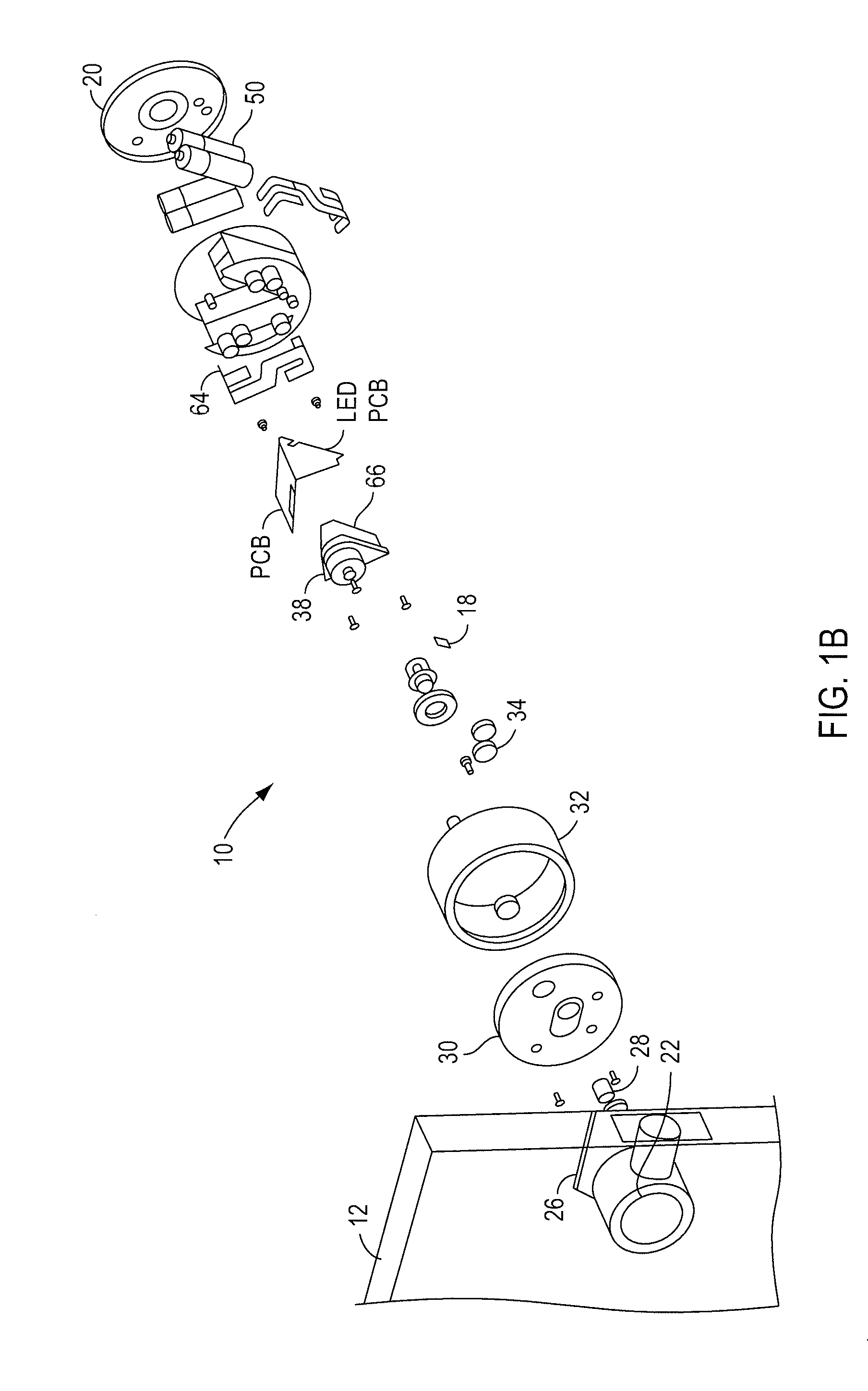
  • Wireless camera with motion detector and face detector

Examples


Embodiment Construction

[0050]As used herein, the term engine refers to software, firmware, hardware, or other component that can be used to effectuate a purpose. The engine will typically include software instructions that are stored in non-volatile memory (also referred to as secondary memory). When the software instructions are executed, at least a subset of the software instructions can be loaded into memory (also referred to as primary memory) by a processor. The processor then executes the software instructions in memory. The processor may be a shared processor, a dedicated processor, or a combination of shared or dedicated processors. A typical program will include calls to hardware components (such as I / O devices), which typically requires the execution of drivers. The drivers may or may not be considered part of the engine, but the distinction is not critical.

[0051]As used herein, the term database is used broadly to include any known or convenient means for storing data, whether centralized or di...


PUM


Abstract

A wireless camera system. One or more wireless bridges include a computing device, an internet-facing radio, and a second radio, a first radio within communication range of the second radio of the wireless bridge, and a third internet-facing radio responsible for transmitting video. One or more cameras are provided. A motion detection device coupled to the one or more cameras. In a first step the motion detection device detects motion of an individual approaching a dwelling, and in a second step if the motion detector detects the approach then the camera is turned on in sufficient time to take a face or body picture of the individual.

Description

FIELD OF THE INVENTION[0001]The present invention is directed to dwelling security systems, and more particularly to a dwelling security system that includes a camera coupled to a WiFi / BTLE a cellular / BTLE bridge that in a first step uses a motion detection to detect motion of an individual approaching a dwelling, and in a second step if the motion detector detects the approach then a camera is turned on in sufficient time to take a face picture of the individual.DESCRIPTION OF THE RELATED ART[0002]Existing security systems for homes and commercial properties feature multiple video camera connected to a security box. The security box contains electronics to convert analog video and optional audio inputs to digital and performs audio and video compression by a System-On-Chip (SoC) processor, which then stores the results on a hard disk. The system could be programmed for continuous recording in a loop, recording upon a trigger caused by external alarm and scene change threshold, or t...

Claims


Application Information

Patent Timeline
IPC IPC(8): G08B13/196H04N7/18G06K9/00H04W4/00H04W4/80
CPCG08B13/19602H04W4/008H04N7/188H04W84/12G06K9/00228G08B13/1966H04W88/16G06K9/00771H04N7/181G08B13/19656G08B13/19695G07C9/00G07C9/00174G07C9/00309G07C9/00896G07C2009/00746H04W4/80G06V40/166G06V40/167G06V20/52
Inventor JOHNSON, JASON
Owner AUGUST HOME
Learn More