Electroluminescent Device

a technology electrode, which is applied in the direction of electroluminescent light source, electroluminescent light source, organic semiconductor device, etc., to achieve the effect of improving the efficiency of light extraction

Inactive Publication Date: 2016-12-08
KONICA MINOLTA INC
View PDF5 Cites 72 Cited by
  • Summary
  • Abstract
  • Description
  • Claims
  • Application Information

AI Technical Summary

Benefits of technology

[0008]Japanese Laid-Open Patent Publication No. 2010-287484 discloses an organic electroluminescent device capable of achieving enhanced efficiency in extraction of light in each color by providing light-emitting layers different in color from one another in each light-emitting unit. A construction for achieving light distribution having desired characteristics at the time when emission from light-emitting units in the same color is combined, however, is unclear.

Problems solved by technology

Similarly to the organic light-emitting device disclosed in Japanese Laid-Open Patent Publication No. 2010-287484, however, a construction for achieving light distribution having desired characteristics at the time when emission from light-emitting units in the same color is combined is unclear.

Method used


Image

  • Electroluminescent Device
  • Electroluminescent Device
  • Electroluminescent Device

Examples


first embodiment

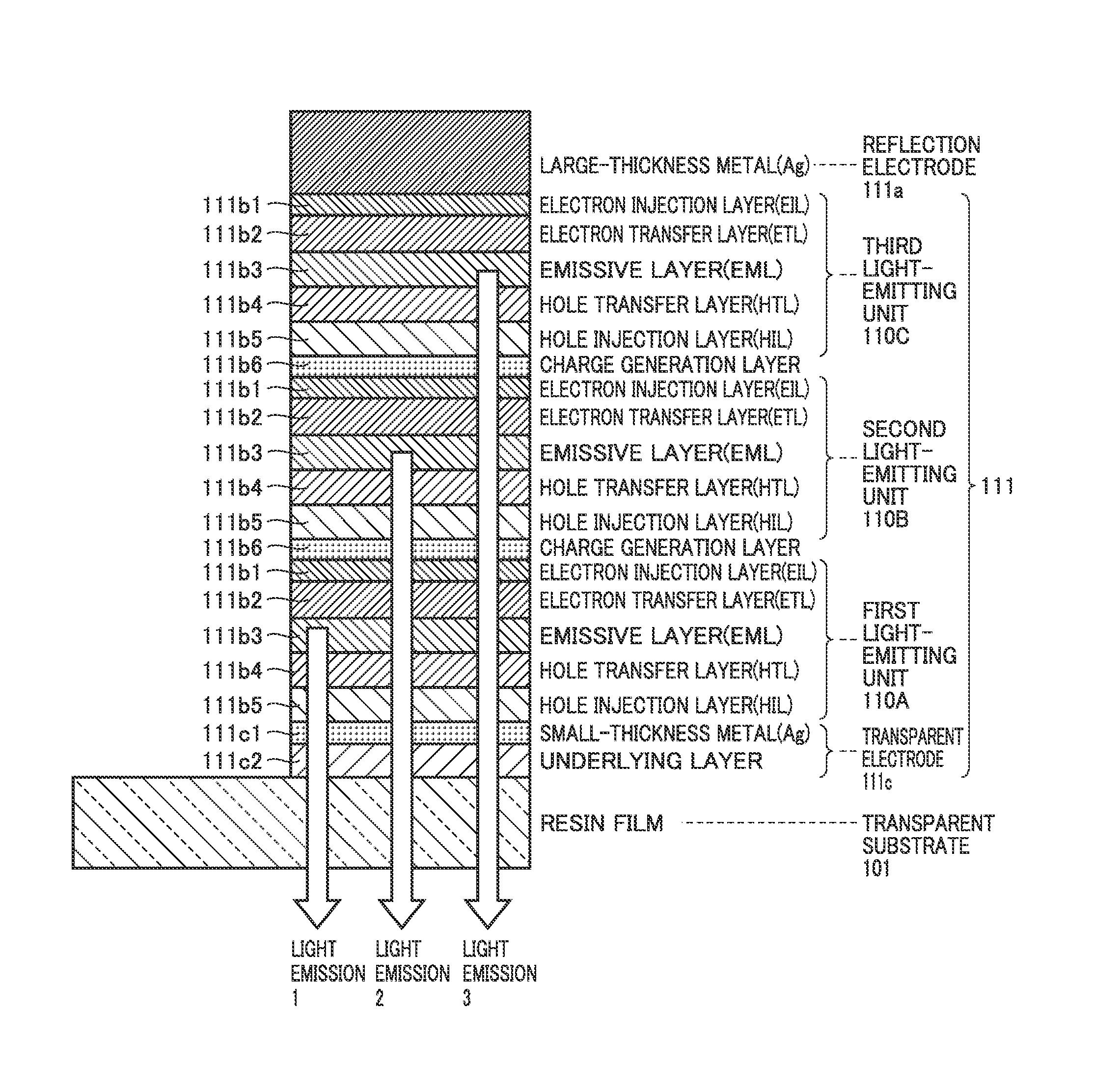
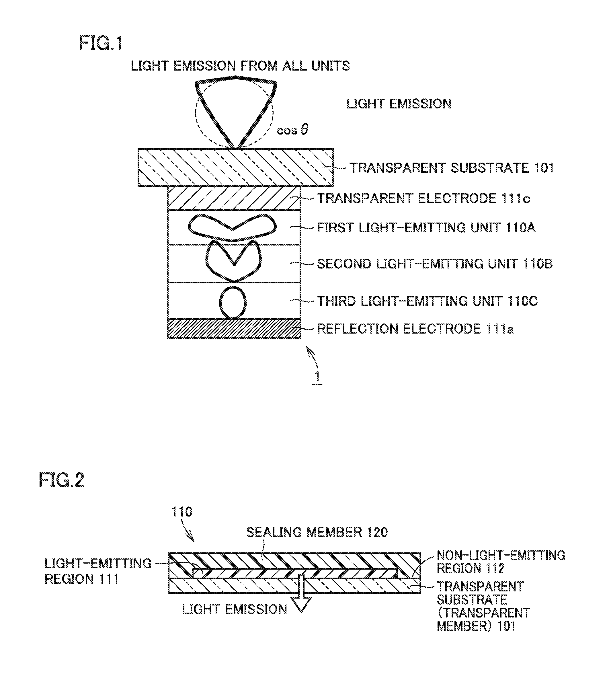
[0052]A general construction of an electroluminescent device 1 in the present embodiment will be described with reference to FIG. 1. FIG. 1 is a cross-sectional view schematically showing electroluminescent device 1 in the present embodiment. Electroluminescent device 1 has such a structure that a transparent electrode 111c, a first light-emitting unit 110A, a second light-emitting unit 110B, a third light-emitting unit 110C, and a reflection electrode 111a are successively stacked on a transparent substrate 101. The light-emitting units are configured to be identical in emission wavelength.

[0053]The electroluminescent device is configured such that a first relative maximal angle or a highest intensity angle when viewed in a front direction of angular dependency of emission intensity in light emission from a light-emitting unit alone is different, and an expression (1) below is satisfied, where D(θ) represents angular dependency (light distribution characteristics) of emission inten...

second embodiment

2.1 Example in which First Relative Maximum of Angular Dependency of Emission Intensity is not Maximal Intensity

[0187]Though the example in which the first relative maximum of angular dependency of emission intensity is defined as the maximal intensity has been described in the embodiment, the present embodiment is not limited thereto. An example in which a relative maximum other than the first relative maximum of angular dependency of emission intensity is defined as the maximal intensity in a case of three light-emitting units will be described below with reference to FIG. 5. A case that the relative maximum other than the first relative maximum of angular dependency of emission intensity is defined as the maximal intensity is desirably designed in the present embodiment such that an angle at which maximal intensity is attained is defined as a peak angle of angular dependency of emission intensity of that light-emitting unit.

[0188]FIG. 25 shows a design example in the model in FIG...

third embodiment

[0196]Though an embodiment of an electroluminescent device of a bottom-emission type has been described so far, the present embodiment is applicable to an electroluminescent device of a top-emission type as shown in FIG. 35. In this case, the side of visual recognition corresponds to a side of sealing member 120 opposite to reflection electrode 111a. In FIG. 35, a concept of a design of each embodiment described so far can be used, by successively providing numbers as light-emitting unit 1, light-emitting unit 2, light-emitting unit 3, and so on from the side where light emission is visually recognized.


PUM


Abstract

An electroluminescent device in which two or more light-emitting units which emit light identical in color are vertically stacked is configured such that a first relative maximal angle or a highest intensity angle viewed in a front direction of angular dependency of emission intensity in light emission from each light-emitting unit alone is different for each light-emitting unit, and D(θ)≧D(0)cos θ(0≦θ≦θD≦60 degrees) . . . Expression (1) is satisfied, where D(θ) represents angular dependency of emission intensity and θD represents a specific angle in simultaneous light emission from all light-emitting units.

Description

[0001]This application is based on Japanese Patent Application No. 2015-112557 filed with the Japan Patent Office on Jun. 2, 2015, the entire content of which is hereby incorporated by reference.BACKGROUND OF THE INVENTION[0002]Field of the Invention[0003]The present embodiment relates to an electroluminescent device.[0004]Description of the Related Art[0005]An electroluminescent device high in luminous efficiency which includes an electroluminescent element such as a light-emitting diode (LED) or organic EL has recently attracted attention. The electroluminescent device is formed from an emissive layer (a light-emitting layer) lying between a planar cathode and a planar anode, and generally in many cases, it is formed from a transparent electrode as an anode and a metal reflection electrode as a cathode. Applications of the electroluminescent device include illumination required to ensure a luminance in a range of specific angles in a specific color, such as a downlight for decorat...

Claims


Application Information

Patent Timeline
Patent Type & Authority Applications(United States)
IPC IPC(8): H01L51/52
CPCH01L51/5278H01L51/5206H01L51/5221H01L2251/5323H01L2251/308H01L2251/301H01L2251/5307H01L51/5253H10K50/11H10K2101/10H05B33/12H10K50/19H10K2102/3023H10K50/13H10K2102/3035H10K2101/00
Inventor OSAWA, KOUSEKINE, KOUJIROU
Owner KONICA MINOLTA INC
Why Eureka
Try Eureka