Power supply apparatus with extending hold up time function
a technology of power supply apparatus and function, which is applied in the direction of emergency power supply arrangement, power supply for data processing, instruments, etc., can solve the problems of not being practical in increasing the bulk capacitor, the design of the modern power supply apparatus is slimmer and lighter today, etc., and achieve the effect of prolonging the hold up time of the power supply apparatus
- Summary
- Abstract
- Description
- Claims
- Application Information
AI Technical Summary
Benefits of technology
Problems solved by technology
Method used
Image
Examples
first embodiment
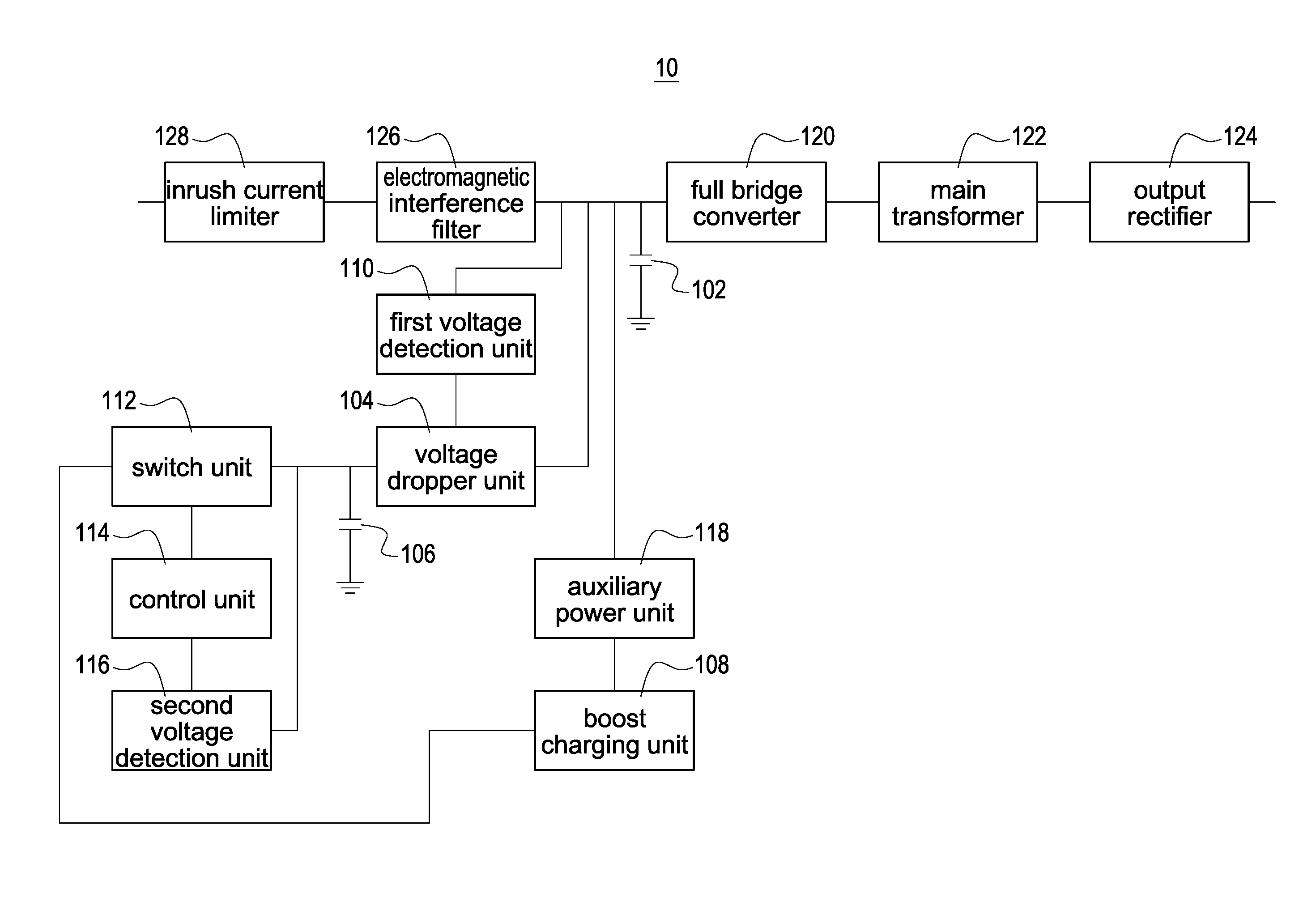
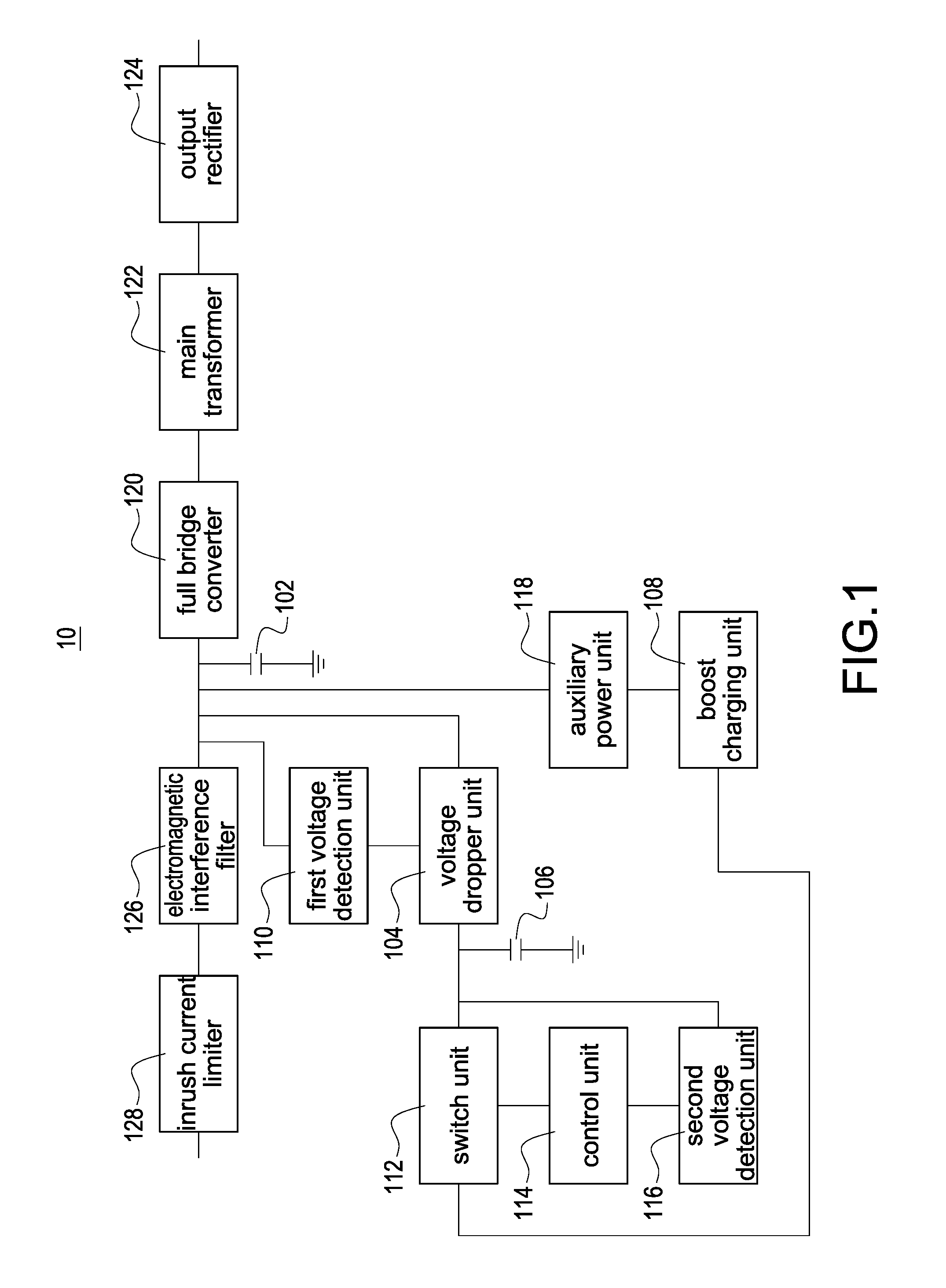
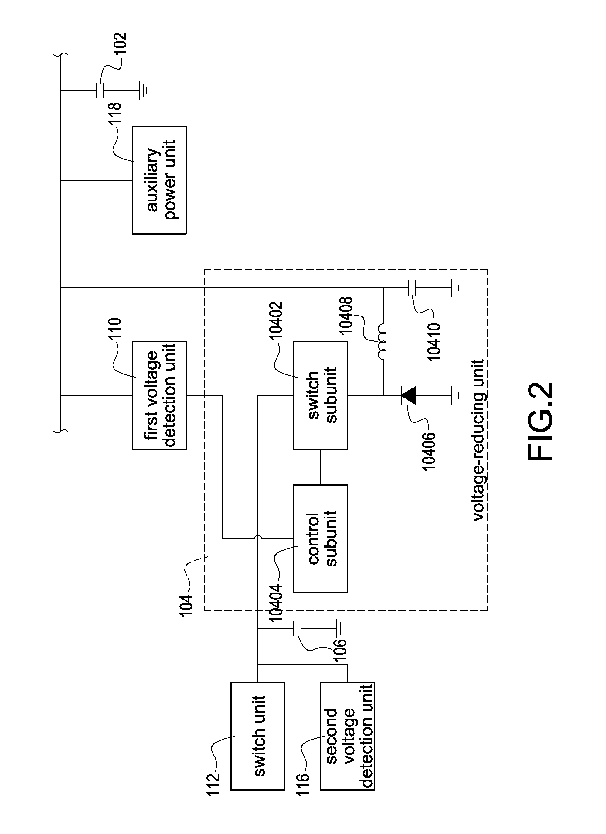
[0015]FIG. 1 shows a block diagram of the power supply apparatus of the present invention. FIG. 2 shows a block diagram of the voltage dropper unit of the present invention. FIG. 3 shows a block diagram of the boost charging unit of the present invention.
[0016]In FIG. 1, a power supply apparatus 10 has a hold up time and comprises a bulk capacitor 102, a pre-charging capacitor 106 and a voltage dropper unit 104. The voltage dropper unit 104 is electrically connected between the bulk capacitor 102 and the pre-charging capacitor 106.
[0017]In this embodiment, when the power supply apparatus 10 receives an input direct current voltage, the bulk capacitor 102 is charged with the input direct current voltage, so that a voltage of the bulk capacitor 102 is provided with a first voltage. The pre-charging capacitor 106 is charged so that the pre-charging capacitor 106 is provided with a second voltage. The second voltage is greater than the first voltage. It is noted that the voltage of the ...
second embodiment
[0030]FIG. 4 shows a block diagram of the power supply apparatus of the present invention. The description for the elements shown in FIG. 4, which are similar to those shown in FIGS. 1-3, is not repeated here for brevity. Moreover, the power supply apparatus 10 further comprises an alternating current to direct current converter 130 electrically connected to the inrush current limiter 128. The alternating current to direct current converter 130 converts an input alternating current voltage into the input direct current voltage.
third embodiment
[0031]FIG. 5 shows a block diagram of the power supply apparatus of the present invention. The description for the elements shown in FIG. 5, which are similar to those shown in FIGS. 1-3, is not repeated here for brevity. Moreover, the power supply apparatus 10 further comprises an output side capacitor 132 and a third diode 134. The output side capacitor 132 is electrically connected to the output rectifier 124. The third diode 134 is electrically connected to the main transformer 122 and the boost charging unit 108.
[0032]When the power supply apparatus 10 receives the input direct current voltage (for example, 40 volts sent through the inrush current limiter 128), a voltage of the output side capacitor 132 is a first voltage (for example, 12 volts), and the pre-charging capacitor 106 is charged so that the pre-charging capacitor 106 is provided with a second voltage (for example, 24 volts), and the second voltage is greater than the first voltage. When the voltage of the output si...
PUM
 Abstract
Description
Claims
Application Information
 - R&D
- Intellectual Property
- Life Sciences
- Materials
- Tech Scout
- Unparalleled Data Quality
- Higher Quality Content
- 60% Fewer Hallucinations
Browse by: Latest US Patents, China's latest patents, Technical Efficacy Thesaurus, Application Domain, Technology Topic, Popular Technical Reports.
© 2025 PatSnap. All rights reserved.Legal|Privacy policy|Modern Slavery Act Transparency Statement|Sitemap|About US| Contact US: help@patsnap.com


