

Resonant conversion apparatus with extended hold-up time and method of operating the same
a technology of resonant conversion and extended hold-up time, which is applied in the direction of electric variable regulation, process and machine control, instruments, etc., can solve the problems of irreversible damage, insufficient time for back-end electronic products to react, and increasing demands on the quality of electronic products. , to achieve the effect of prolonging the hold-up tim
- Summary
- Abstract
- Description
- Claims
- Application Information
AI Technical Summary
Benefits of technology
Problems solved by technology
Method used
Image

Examples
first embodiment
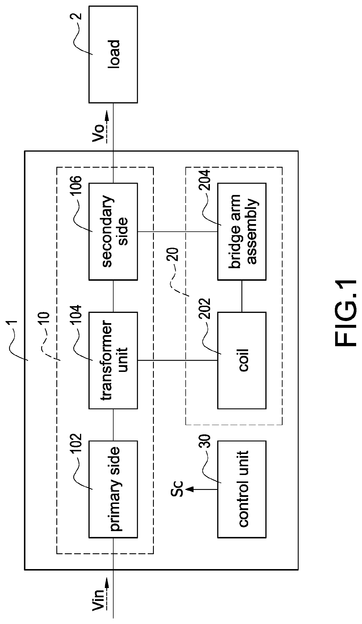
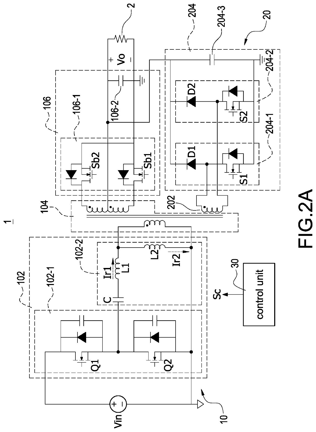
[0020]Please refer to FIG. 2A, which is a block circuit diagram of the resonant conversion apparatus with extended hold-up time according to the present disclosure, and also refer to FIG. 1. The primary side 102 has a switching unit 102-1 and a resonant unit 102-2. The switching unit 102-1 receives the input voltage Vin, and the resonant unit 102-2 is coupled to the switching unit 102-1 and a primary side of the transformer unit 104. The secondary side 106 has a rectifying unit 106-1 and an output capacitor 106-2. The rectifying unit 106-1 is coupled to a secondary side of the transformer unit 104. The output capacitor 106-2 is coupled to the rectifying unit 106-1 and the bridge arm assembly 204 for stabilizing a voltage value of the output voltage Vo. The bridge arm assembly 204 has a first bridge arm 204-1, a second bridge arm 204-2, and an energy-storing capacitor 204-3 coupled in parallel to each other. The first bridge arm 204-1 has a first diode D1 and a first switch S1 connec...
second embodiment
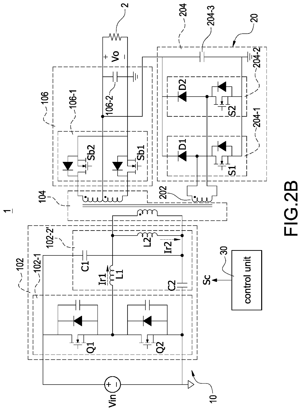
[0025]Please refer to FIG. 2B, which is a block circuit diagram of the resonant conversion apparatus with extended hold-up time according to the present disclosure, and also refer to FIG. 2A. The major difference between the resonant conversion apparatus 1 shown in FIG. 2B and that shown in FIG. 2A is that a resonant unit 102-2′ of the former is a dual-capacitor resonant unit and the resonant unit 102-2 of the latter is a single-capacitor resonant unit. In other words, the single-capacitor resonant unit 102-2 shown in FIG. 2A has only a resonant capacitor C coupled to an upper switch Q1 and a lower switch Q2 of the switching unit 102-1, and a first resonant inductor L1; the dual-capacitor resonant unit 102-2′ shown in FIG. 2B has two series-connected resonant capacitors C1, C2 coupled to the upper switch Q1 and the lower switch Q2 of the switching unit 102-1, and a second resonant inductor L2. In comparison with the single resonant capacitor C, two resonant capacitors C1, C2 are use...
PUM
 Abstract
Description
Claims
Application Information