Method of Making Aluminum or Magnesium Based Composite Engine Blocks or Other Parts With In-Situ Formed Reinforced Phases Through Squeeze Casting or Semi-Solid Metal Forming and Post Heat Treatment

a technology of aluminum or magnesium based composite engine blocks and other parts, applied in the direction of engine components, mechanical equipment, etc., can solve the problems of high cost, inability to meet the requirements of production, so as to achieve the effect of improving mechanical properties

Inactive Publication Date: 2016-12-15
GM GLOBAL TECH OPERATIONS LLC
View PDF0 Cites 19 Cited by
  • Summary
  • Abstract
  • Description
  • Claims
  • Application Information

AI Technical Summary

Benefits of technology

[0007]To satisfy the above need, the present inventors have determined that the in-situ nucleation and growth of a reinforcing phase in a lightweight metallic alloy to make a composite may be triggered by an activating event of an added precursor material that occurs during a squeeze casting or SSM forming approach. One preferred form of such an activating event is a thermal one, where the precursor is exposed to an elevated temperature during the component-forming process. Regardless of the activa

Problems solved by technology

Nevertheless, it is known that the mechanical properties of cast components are often inferior to their wrought counterparts, due in no small part to porosity and related defects that are inherent in (or at least hard to avoid) known casting processes.
Unfortunately, high-volume production and shape complexity considerations may render wrought options cost-prohibitive, if not outright impossible.
Moreover, the billets used in this and related thixotropic processes are a highly specialized (and therefore expensive) way to achieve the desirable non-dendritic (i.e., globular) microstructure.
One of the difficulties associated with creating such engineered composites is th

Method used


Image

  • Method of Making Aluminum or Magnesium Based Composite Engine Blocks or Other Parts With In-Situ Formed Reinforced Phases Through Squeeze Casting or Semi-Solid Metal Forming and Post Heat Treatment
  • Method of Making Aluminum or Magnesium Based Composite Engine Blocks or Other Parts With In-Situ Formed Reinforced Phases Through Squeeze Casting or Semi-Solid Metal Forming and Post Heat Treatment
  • Method of Making Aluminum or Magnesium Based Composite Engine Blocks or Other Parts With In-Situ Formed Reinforced Phases Through Squeeze Casting or Semi-Solid Metal Forming and Post Heat Treatment

Examples


Embodiment Construction

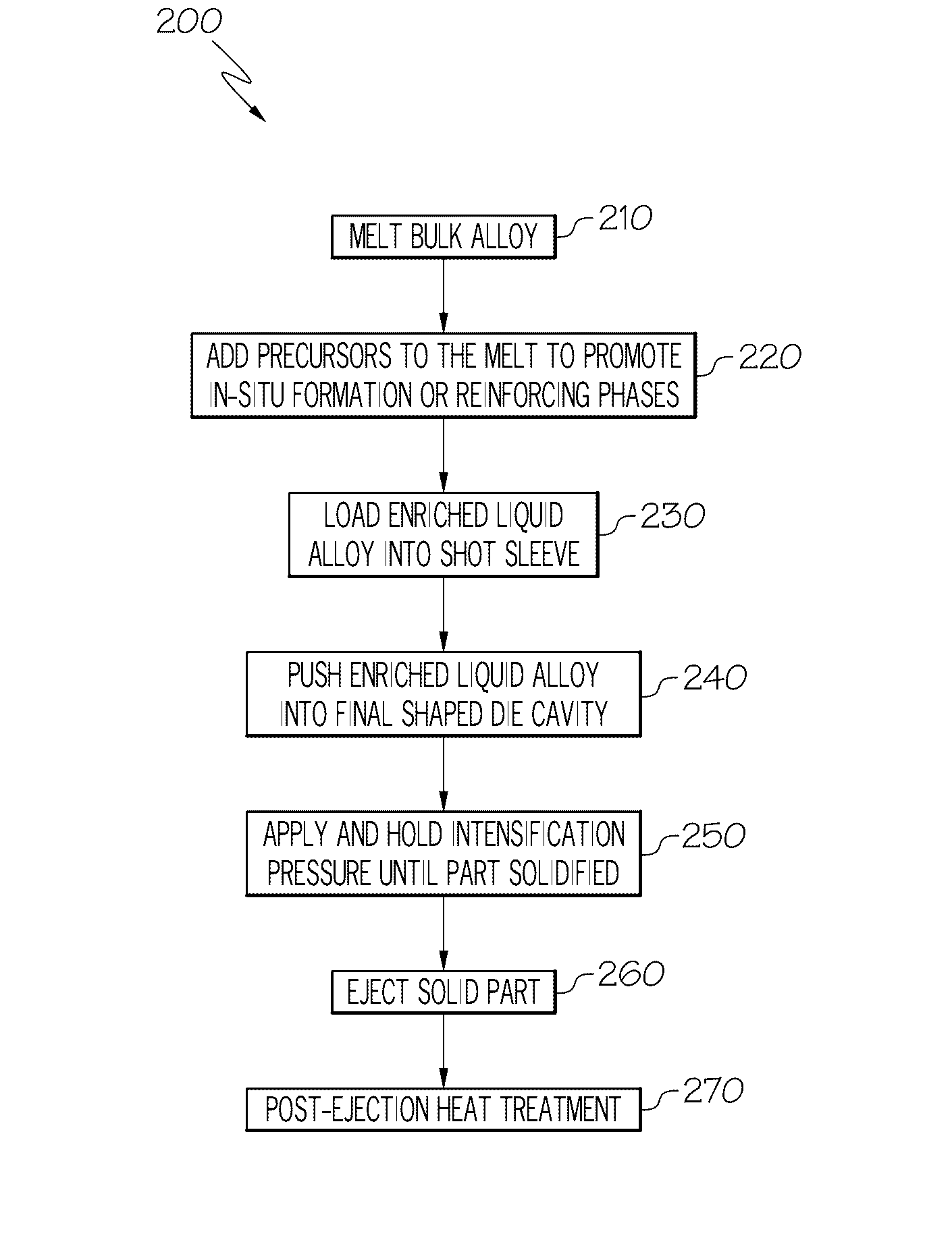
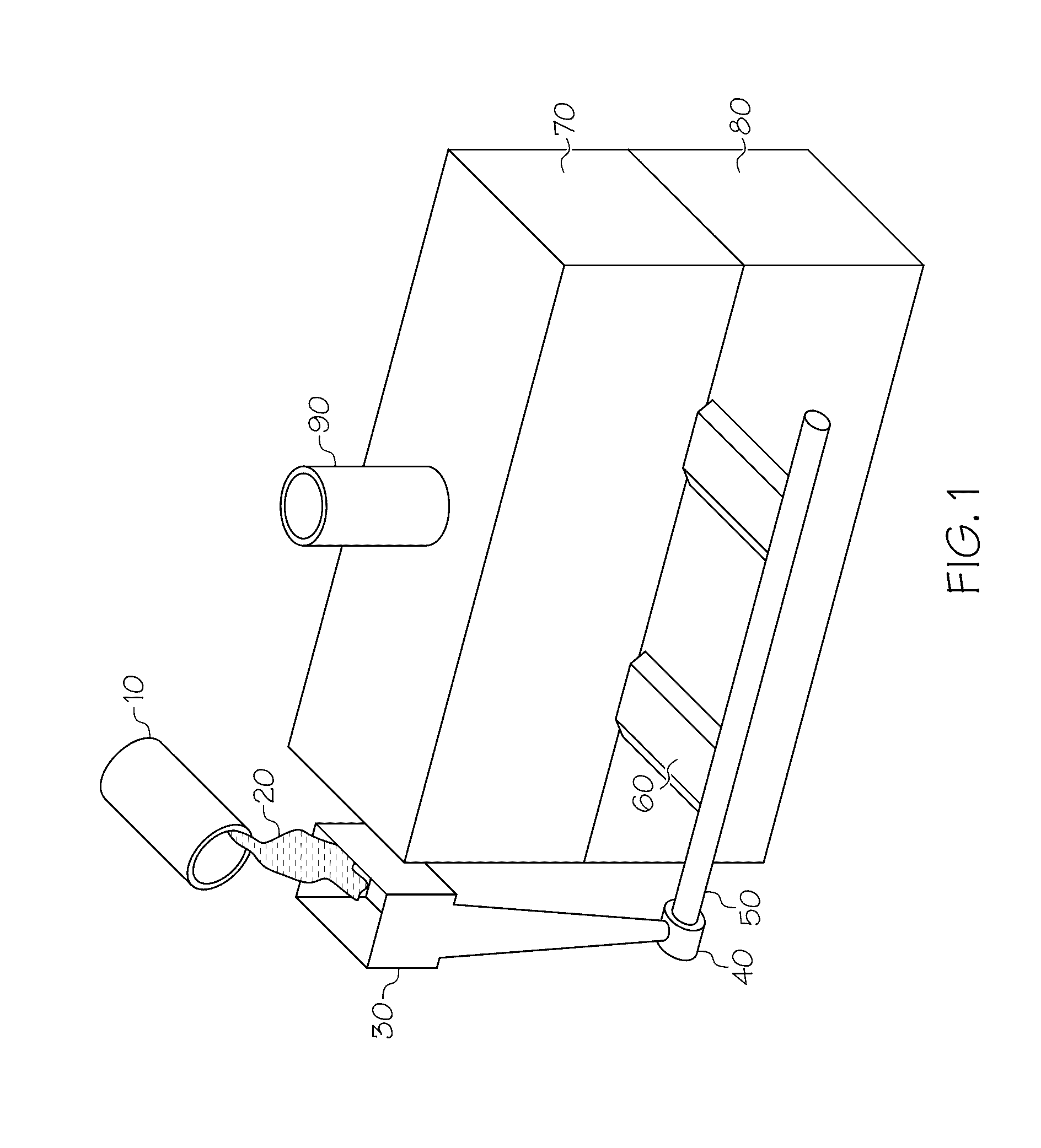
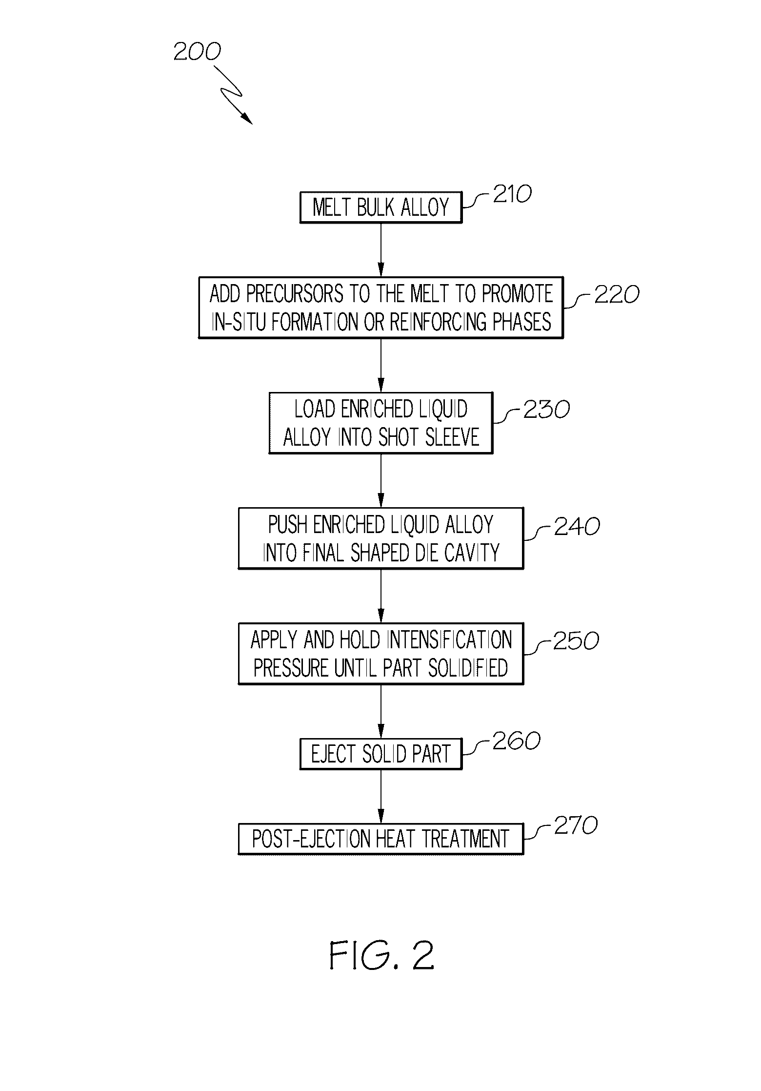
[0017]Referring first to FIGS. 1 and 4, a representative casting approach similar to high pressure die casting shows a ladle 10 used to pour a molten metal 20 into a pouring basin 30 and down a sprue that terminates into a well 40. A shot sleeve 50 takes molten metal and delivers it under increased pressure (such as through a plunger (not shown)) to a series of gates 60 that feed a separable cope 70 and drag 80 that act as a housing for a die cavity therein that defines the representative shape of the component, such as engine block 100 that is depicted with particularity in FIG. 4. Intricate features, including—among other things—a crankcase 110, crankshaft bearing 120, camshaft bearing 130 (in the case of engines with overhead valves and pushrods), water cooling jackets 140, flywheel housing 150 and cylinder bores 160 may be defined by the cavity. A riser (also called a feeder) 90 is also included in the cope 70 in order to feed the casting to compensate for shrinkage that may occ...


PUM

PropertyMeasurementUnit
Temperatureaaaaaaaaaa
Timeaaaaaaaaaa
Pressureaaaaaaaaaa

Abstract

A method of making a reinforced metal alloy component, the method including introducing a reinforcing phase precursor into a bulk alloy that is selected from the group consisting of high-entropy alloys, aluminum-based alloys, magnesium-based alloys and combinations thereof. The precursor is converted to a reinforcing phase by exposing the bulk alloy and precursor to an elevated temperature during one or more of a subsequent heat treating step, squeeze casting shaping or semi-solid metal shaping.

Description

BACKGROUND TO THE INVENTION[0001]This invention relates generally to a method to make light-weight metal-matrix composite components through squeeze casting or semi-solid metal (SSM) forming, and more particularly to making such components from a reinforced metal matrix composite where the reinforcing phase or phases are generated in-situ during such casting or forming operations.[0002]Casting has become the dominant form of metal-forming operations for the manufacture of repeatable (i.e., high-volume) components (particularly those that employ lightweight metal alloys such as aluminum or magnesium), and includes numerous variants, such as die casting, permanent mold casting, sand casting, plaster casting, investment casting or the like. Nevertheless, it is known that the mechanical properties of cast components are often inferior to their wrought counterparts, due in no small part to porosity and related defects that are inherent in (or at least hard to avoid) known casting process...

Claims


Application Information

Patent Timeline
IPC IPC(8): B22D27/20C22F1/06B22D17/00C22C1/10B22D21/00B22D25/02C22C1/02C22F1/04B22D17/08
CPCB22D27/20C22F1/04C22F1/06B22D17/007C22C1/1036B22D21/007B22D25/02C22C1/026B22D17/08B22D17/00C22C1/02C22C1/12B22F5/008C22C1/0408C22C1/0416C22C32/00B22F2998/10B22F2999/00C22C1/1073B22F2003/248B22F2202/01B22F2202/07
Inventor WANG, YUCONGOSBORNE, RICHARD J.MCCLORY, BRIAN J.
Owner GM GLOBAL TECH OPERATIONS LLC
Why Eureka
Try Eureka