Network Regulation Upon Threshold Value Overshoots in a Low Voltage or Medium Voltage Network

Active Publication Date: 2016-12-15
SIEMENS AG
View PDF7 Cites 3 Cited by
  • Summary
  • Abstract
  • Description
  • Claims
  • Application Information

AI Technical Summary

Benefits of technology

[0042]The conventional methods are therefore replaced with a method in accordance with the invention to ensure the network integration of flexibility providers that operate freely on markets, where the action instructions us

Problems solved by technology

The classic power supply operation for electrical supply is facing great challenges due to the increasing establishment of decentralized, mostly renewable, energy generating plants (DEA, typically in the power range from 3 to 100 kW).
This arises from the fact that many renewable energy sources (wind, solar, water) are available only depending on the situation and not according to pre-determined timetables.
Network bottlenecks can arise because the participation in energy markets and the use of internal storage units (which are not recognizable from the network viewpoint because they are located, for example, within buildings or industrial sites) can alter the previous temporal distribution of the load (e.g., according to the standard load profile HO).
The

Method used


Image

  • Network Regulation Upon Threshold Value Overshoots in a Low Voltage or Medium Voltage Network
  • Network Regulation Upon Threshold Value Overshoots in a Low Voltage or Medium Voltage Network
  • Network Regulation Upon Threshold Value Overshoots in a Low Voltage or Medium Voltage Network

Examples


first embodiment

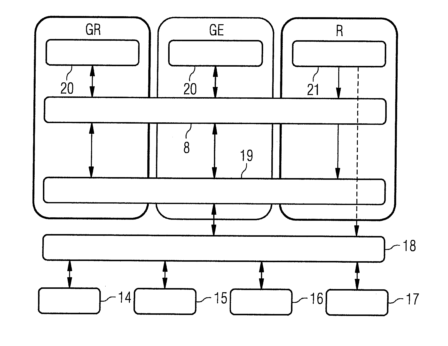
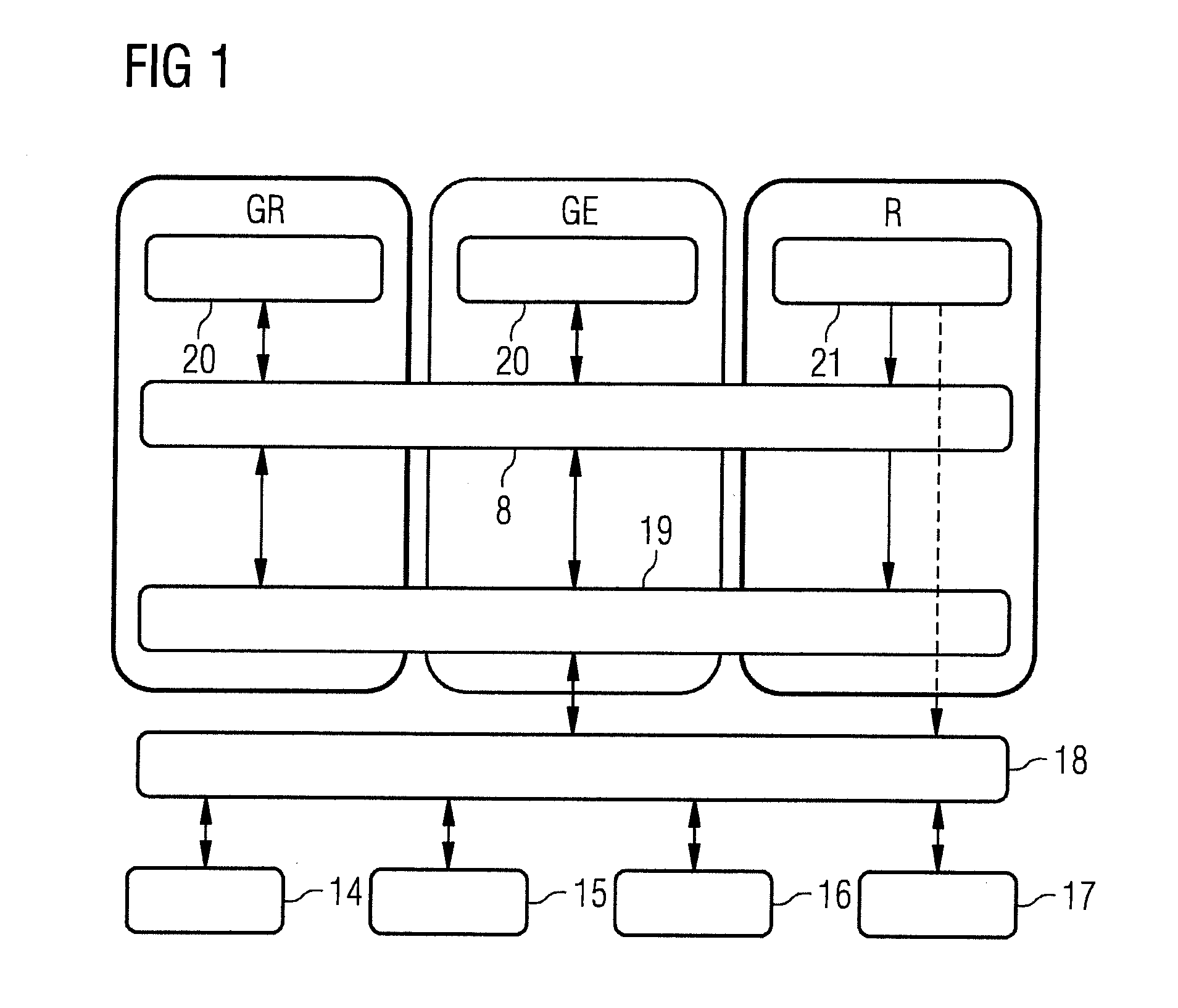
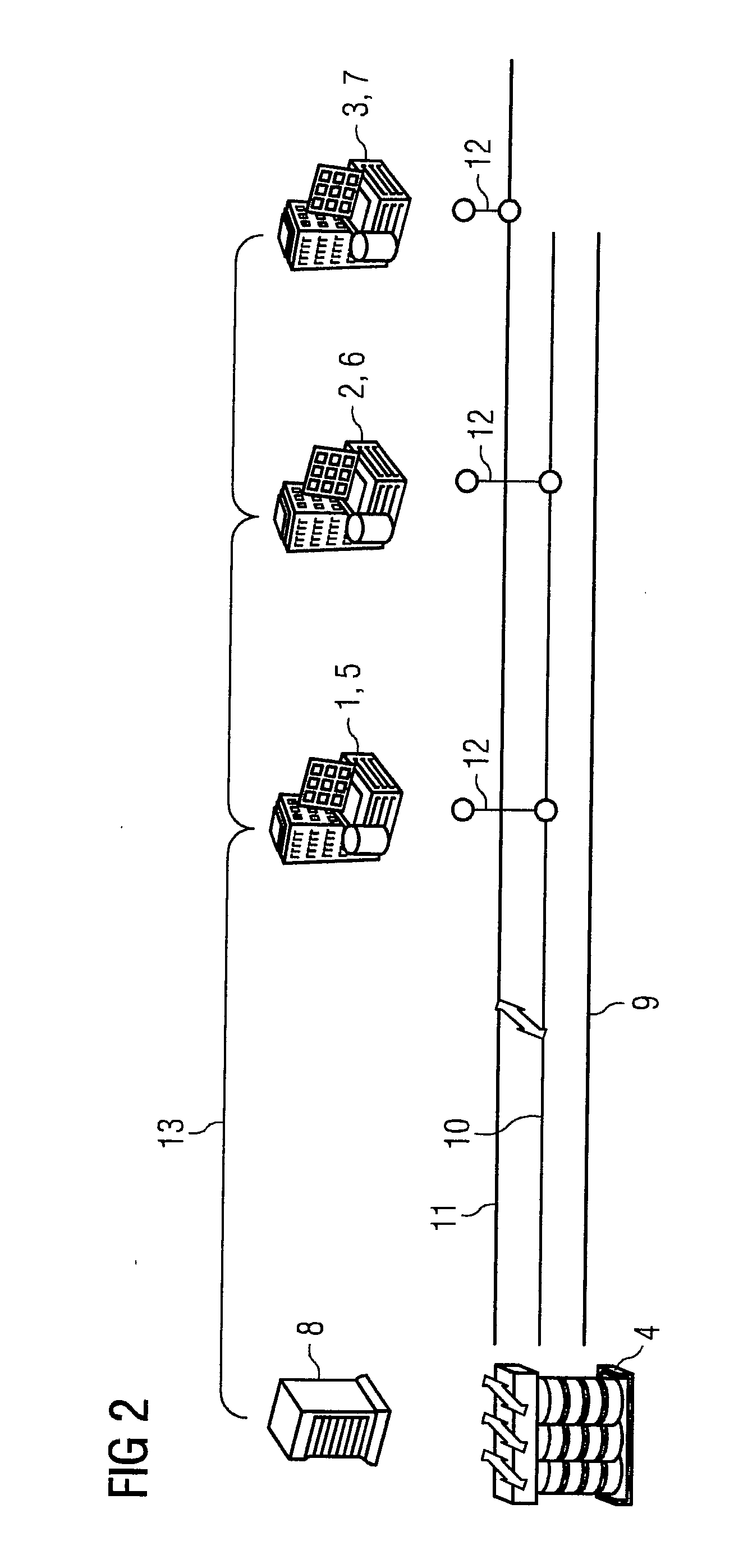
[0059]In the method, all the building automation systems 5, 6, 7 receive the same action instruction with the same probability factor. Only a different selection factor of the individual building automation systems 5, 6, 7 can cause the smart buildings 1, 2, 3 to contribute with different priority to the rectifying of the threshold value overshoot.

[0060]However, the smart building 3 can contribute nothing by complying with the action instruction, because it is not connected to the affected conductor strand 10. If the smart buildings 1, 2 do not have sufficient emergency reserves, the problem cannot be solved by the smart buildings 1, 2 and the central regulation unit 8 must notify this to the central site of the network operator. A disadvantage of the first embodiment of the method is that all the smart buildings 1, 2, 3 supply the maximum emergency reserve without solving the problem.

second embodiment

[0061]In the method, in which the topology of the low voltage network is known in relation to the building automation systems 5, 6, 7, the individual building automation systems 5, 6, 7 receive different action instructions, but with the same probability factor. An action instruction to a building automation system could therefore be “reduce effective power xy kW”, whilst the action instruction to another building automation system is “reduce effective power yz kW”, possibly also depending on the topology.

[0062]For this purpose, the central regulation unit 8 can have a topology model and, based thereon, select individual smart buildings 1, 2, 3 or a group. This can occur, for example, via a contribution matrix in which the effectiveness of individual smart buildings 1, 2, 3 at particular network nodes is stored. In order that in this case a particular certainty factor or a particular fairness can also be implemented, the group is not reduced to the smallest possible (e.g., not to on...


PUM


Abstract

A method for network regulation upon threshold value overshoots in a low voltage or medium voltage network, wherein control commands are transmitted from a central regulation unit of the low or medium voltage network to controllable components of the low voltage or medium voltage network, where upon occurrence of the threshold value overshoot, the central regulation unit calculates the necessary correction and transmits a suitable action instruction to at least one controllable component, with each action instruction, a probability factor is also transmitted which is incrementally raised if, given an insufficient reaction of the controllable components, the threshold value overshoot is not prevented and thus an action instruction must be transmitted anew, and the central regulation unit informs the network operator if the emergency reserves of the controllable components are insufficient to prevent the threshold value overshoot.

Description

BACKGROUND OF THE INVENTION[0001]1. Field of the Invention[0002]The invention relates to a method for network regulation upon threshold value overshoots in a low voltage or medium voltage network, where control commands are transmitted from a central regulation unit of the low voltage or medium voltage network to controllable components of the low voltage or medium voltage network. The invention can be used respectively for just a low voltage network or just a medium voltage network.[0003]2. Description of the Related Art[0004]Low voltage networks are part of the power network for distribution of the electrical energy to the majority of the electrical consumers, which consists of low voltage devices. In order to prevent voltage losses, low voltage networks are restricted in their spatial extent to a region from a few 100 m to a few kilometers. They are therefore fed regionally via transformer stations from a higher-order medium voltage network. In Europe, they are typically operated...

Claims


Application Information

Patent Timeline
IPC IPC(8): G05B19/042
CPCG05B2219/2639G05B19/042H02J3/12H02J3/32Y04S10/123Y04S10/14H02J3/001H02J2300/20H02J3/381H02J13/00034Y02E40/70Y02E60/00H02J2300/22Y02E70/30Y04S10/52
Inventor EINFALT, ALFREDGAWRON-DEUTSCH, TOBIAS
Owner SIEMENS AG
Why Eureka
Try Eureka