Copper alloy twisted wire, method for manufacturing same, and electric wire for automobile

a technology of copper alloy and twisted wire, which is applied in the direction of metal/alloy conductors, conductors, and conductors, etc., can solve the problems of not being able to twist the wire, the workability of copper alloy material significantly decreases, and the wire may have low wire twistability, so as to reduce the influence of work hardening, good strength and elongation, and soften the intermediate wire material

Inactive Publication Date: 2016-12-22
AUTONETWORKS TECH LTD +2
View PDF5 Cites 12 Cited by
  • Summary
  • Abstract
  • Description
  • Claims
  • Application Information

AI Technical Summary

Benefits of technology

[0019]The method for manufacturing a copper alloy twisted wire has the above-described steps. Therefore, according to this method for manufacturing a copper alloy twisted wire, it is possible to obtain a copper alloy twisted wire constituted by soft single wires having a specific chemical component composition that contains the above-described specific additional elements in a specific range. Therefore, with this method for manufacturing a copper alloy twisted wire, it is possible to manufacture a copper alloy twisted wire having good strength and elongation.
[0020]Moreover, in the method for manufacturing a copper alloy twisted wire, since the intermediate wire material is annealed, the influence of work hardening caused by wiredrawing or the like before annealing is lessened, and a softened intermediate wire material can be obtained. Also, with this method for manufacturing a copper alloy twisted wire, a single wire is obtained by wiredrawing the annealed intermediate wire material at a cold deformation degree in a range of at least 77% and less than 99%. Therefore, according to this method for manufacturing a copper alloy twisted wire, compared to the case where the intermediate wire material is not a

Problems solved by technology

However, if the content of additional elements is at least 1 mass % in total, the workability of the copper alloy material significantly decreases.
However, since in the conventional method for manufacturing a copper alloy twisted w

Method used


Image

  • Copper alloy twisted wire, method for manufacturing same, and electric wire for automobile
  • Copper alloy twisted wire, method for manufacturing same, and electric wire for automobile

Examples


working example 1

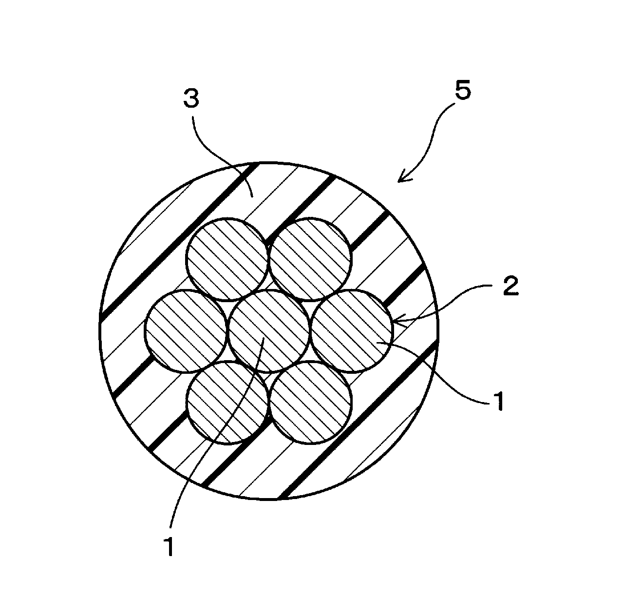
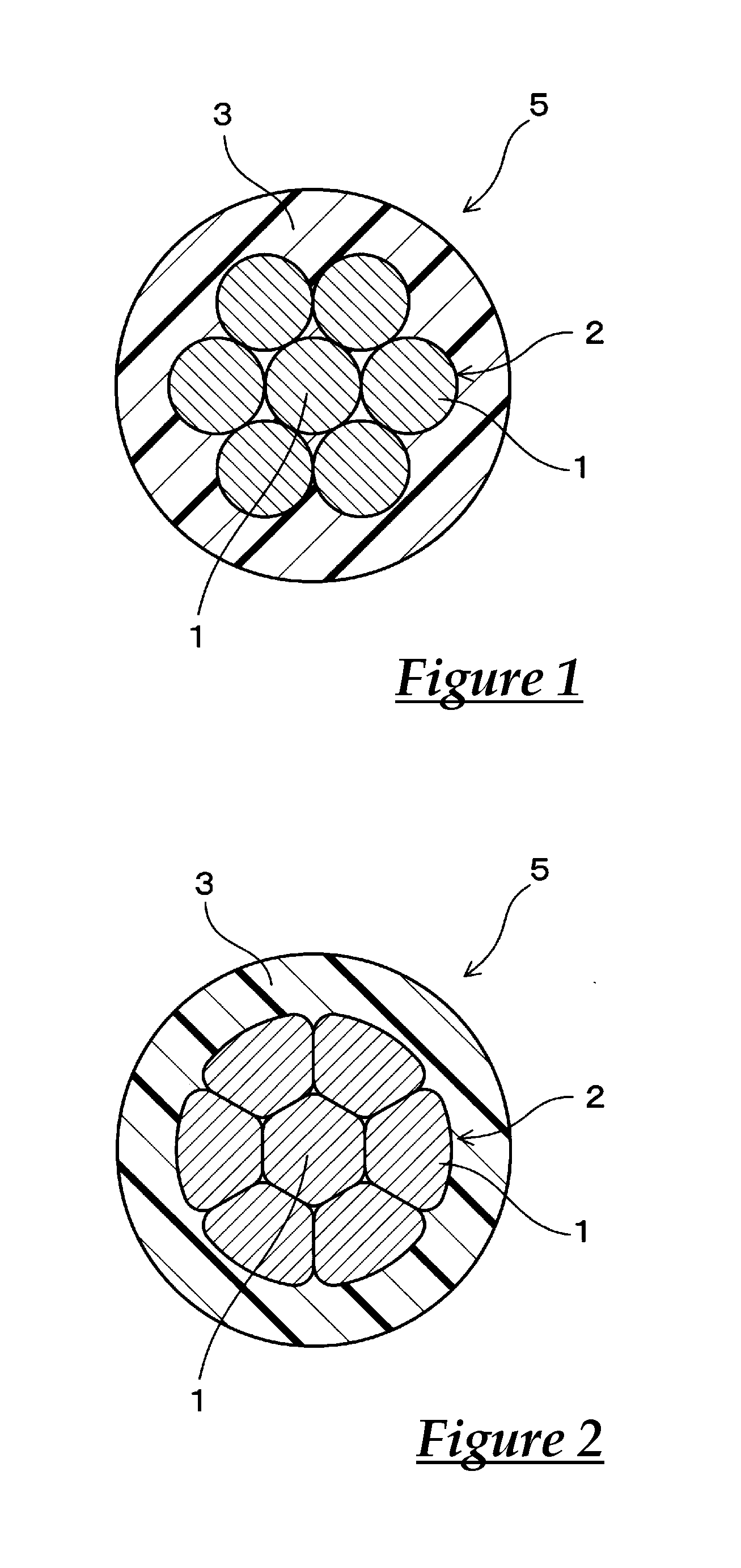
[0057]In this example, copper alloy twisted wires were produced by twisting seven single wires made of a copper alloy and having a chemical component composition shown in Table 1, which were then evaluated.

[0058]The copper alloy twisted wires were produced by performing a step of forming a cast material having a chemical component composition that contains at least one additional element selected from the group consisting of Fe, Ti, Sn, Ag, Mg, Zn, Cr, and P in a total amount of at least 1.0 mass % and not more than 2.0 mass % and in which a remaining portion includes Cu and inevitable impurities, a step of forming an expanded material by subjecting the cast material to plastic forming, a step of forming an intermediate wire material by wiredrawing the expanded material, a step of annealing the intermediate wire material, a step of forming a single wire by wiredrawing the annealed intermediate wire material at a cold deformation degree in a range of at least 77% and less than 99%, a...


PUM

PropertyMeasurementUnit
Fractionaaaaaaaaaa
Fractionaaaaaaaaaa
Fractionaaaaaaaaaa

Abstract

A cast material is formed, the cast material having a chemical component composition that contains at least one additional element selected from the group consisting of Fe, Ti, Sn, Ag, Mg, Zn, Cr, and P in an amount of at least 1.0 mass % and not more than 2.0 mass % in total, and in which a remaining portion includes Cu and inevitable impurities. An expanded material is formed by subjecting the cast material to plastic forming. An intermediate wire material is formed by wiredrawing the expanded material. The intermediate wire material is annealed. A single wire is formed by wiredrawing the annealed intermediate wire material at a cold deformation degree in a range of at least 77% and less than 99%. A twisted wire is formed by twisting a plurality of single wires, and the twisted wire is heated. Accordingly, a copper alloy twisted wire is obtained.

Description

CROSS REFERENCE TO RELATED APPLICATIONS[0001]This application claims the priority of Japanese patent application JP2014-038588 filed on Feb. 28, 2014, the entire contents of which are incorporated herein.Technical Field[0002]The present invention relates to a copper alloy twisted wire, a method for manufacturing the same, and an electric wire for an automobile, and more specifically relates to a copper alloy twisted wire for use as a conductor of an electric wire for an automobile, a method for manufacturing the same, and an electric wire for an automobile.Background Art[0003]Conventionally, an electric wire for an automobile having a conductor and an insulator with which an outer circumference of the conductor is coated is known. In general, a copper alloy twisted wire obtained by twisting a plurality of single wires made of a copper alloy is used as the above-described conductor.[0004]In recent years, following a reduction in the weight of automobiles, there is a demand for a redu...

Claims


Application Information

Patent Timeline
IPC IPC(8): B21C1/02C22C9/00H01B13/02B60R16/02H01B1/02H01B13/00C22F1/08B21C1/00
CPCB21C1/02C22F1/08C22C9/00H01B13/02B60R16/02H01B1/026H01B13/0016B21C1/003
Inventor KOBAYASHI, HIROYUKI
Owner AUTONETWORKS TECH LTD
Why Eureka
Try Eureka