SUPPORT ARRANGEMENT DETERMINING APPARATUS, THREE-DIMENSIONAL PRINTING SYSTEM, AND METHOD of DETERMINING SUPPORT ARRANGEMENT

a technology of support arrangement and determining apparatus, which is applied in the direction of program control, total factory control, instruments, etc., can solve the problem that the resin layer with a small cross-sectional area may not be able to support the load of all the resin layers therein, and achieve the effect of reducing the computational burden, and reducing the amount of data

Inactive Publication Date: 2016-12-22
ROLAND DG CORP
View PDF6 Cites 6 Cited by
  • Summary
  • Abstract
  • Description
  • Claims
  • Application Information

AI Technical Summary

Benefits of technology

[0009]In the arrangement determining apparatus, the tilting processor tilts the three-dimensional model so that the principal axis of the three-dimensional model is parallel or substantially parallel to the horizontal plane. The principal axis is the line connecting the center of gravity of the three-dimensional model with a farthest point that is one of the points on the outer circumferential surfaces of the three-dimensional model and that is most distant from the center of gravity of the three-dimensional model. This enables the top surface or the bottom surface of the three-dimensional model that has been tilted by the tilting processor to have a sufficient but not excessive area for providing and attaching the supports in such a number or amount that is necessary to support the load of the target object. As a result, the supports are attached and arranged in a number or amount that is necessary to support the load of the target object on the top surface or the bottom that is allowed to have an area necessary to attach the supports, so that the supports sufficiently support the load of the target object during object formation. The supports are attached and arranged in an optimum manner.
[0011]The present preferred embodiment enables the supports to be attached and arranged on a surface of the three-dimensional model that contains the nearest point, which is the closest point from the center of gravity of the three-dimensional model. In other words, it is possible to shorten the distance between the center of gravity of the three-dimensional model and the surface of the three-dimensional model on which the supports are to be formed. The closer the center of gravity of the three-dimensional model is to the surface on which the supports are to be arranged, the more stable the target object is during object formation. Thus, the three-dimensional printing apparatus is able to form the target object and the supports for the target object being in a stable state.
[0013]In some cases, the target object to be formed may include a surface on which no support should be attached or arranged. In various preferred embodiments of the present invention, the surface of the target object on which no support should be attached or arranged is defined as a forbidden surface. The present preferred embodiment enables the rotation processor not to set the nearest point on the forbidden surface. As a result, the supports are able to support the load of the target object without attaching and arranging the supports on the forbidden surface.
[0015]In the present preferred embodiment, the principal axis setting processor sets the principal axis of the three-dimensional model using the centers of gravity of the plurality of polygons that have already been calculated by the center-of-gravity calculating processor. Therefore, the principal axis setting processor does not need to calculate the centers of gravity of the plurality of polygons again. This allows the principal axis setting processor to reduce the process time required to set the principal axis of the three-dimensional model.
[0017]The present preferred embodiment makes it possible to reduce the amount of data of the three-dimensional model by smoothing the three-dimensional model with the pre-processing processor. Therefore, the reference processor, the center-of-gravity calculating processor, the principal axis setting processor, the tilting processor, the rotation processor, and the arranging processor are allowed to use a three-dimensional model whose amount of data is reduced by the pre-processing processor. As a result, the computational burden is lowered in a desirable manner.

Problems solved by technology

If there is a resin layer with a small cross-sectional area, it is possible that the resin layer with a small cross-sectional area may not be able to support the load of all the resin layers therebelow.

Method used


Image

  • SUPPORT ARRANGEMENT DETERMINING APPARATUS, THREE-DIMENSIONAL PRINTING SYSTEM, AND METHOD of DETERMINING SUPPORT ARRANGEMENT
  • SUPPORT ARRANGEMENT DETERMINING APPARATUS, THREE-DIMENSIONAL PRINTING SYSTEM, AND METHOD of DETERMINING SUPPORT ARRANGEMENT
  • SUPPORT ARRANGEMENT DETERMINING APPARATUS, THREE-DIMENSIONAL PRINTING SYSTEM, AND METHOD of DETERMINING SUPPORT ARRANGEMENT

Examples


Embodiment Construction

[0040]Hereinbelow, three-dimensional printing systems including support arrangement determining apparatuses according to preferred embodiments of the present invention, as well as methods of determining a support arrangement, will be described with reference to the drawings. The preferred embodiments described herein are not intended to limit the present invention. The features, components and steps that exhibit the same effects are denoted by the same reference symbols, and repetitive description thereof may be omitted as appropriate.

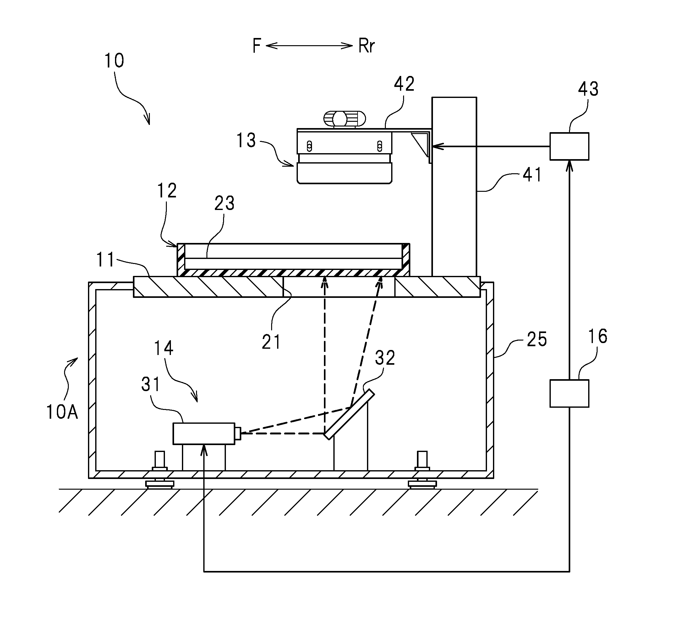
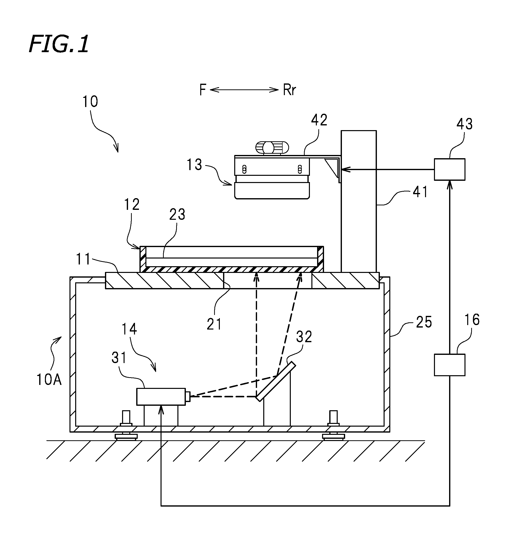
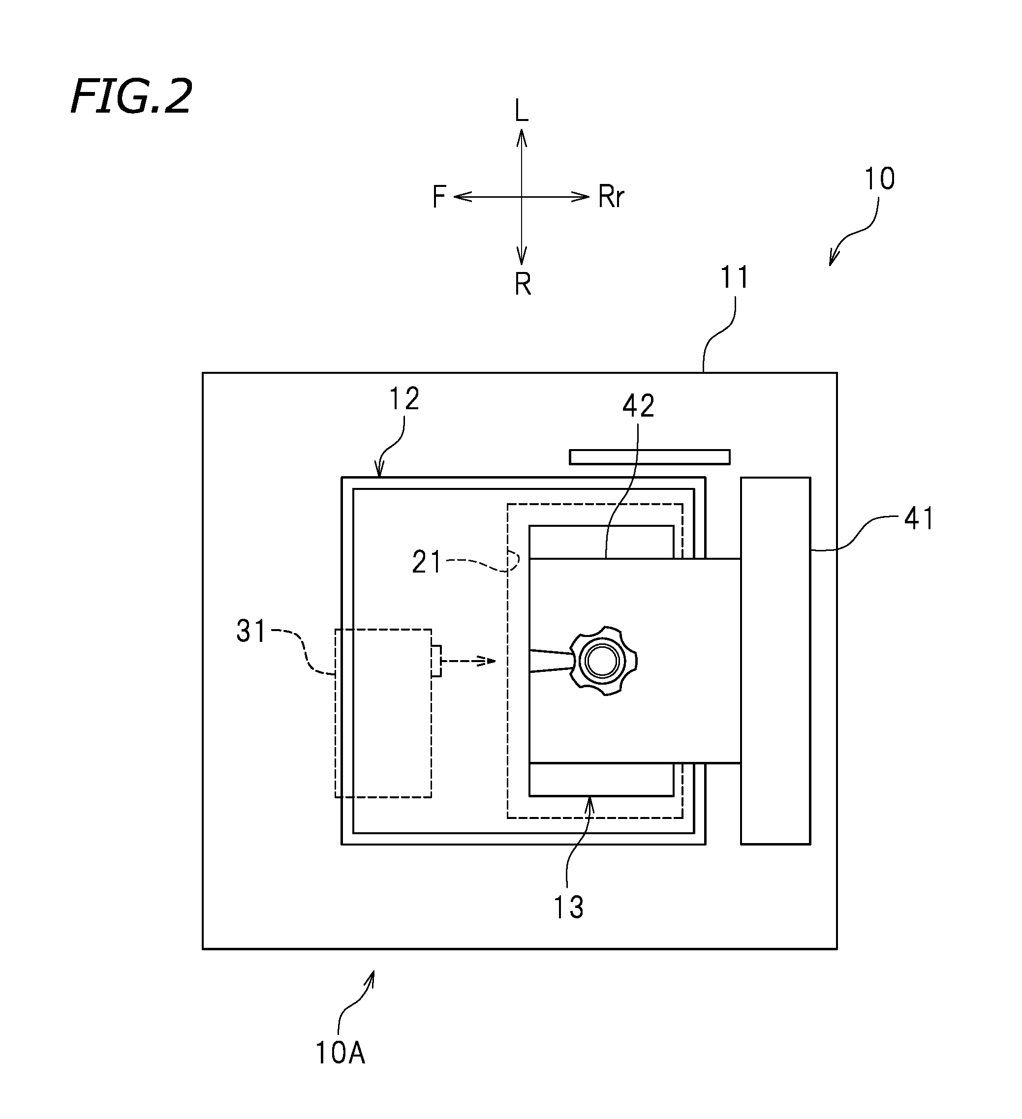
[0041]FIG. 1 is a cross-sectional view of a three-dimensional printing system 10 according to the present preferred embodiment. FIG. 2 is a plan view of the three-dimensional printing system 10. In the drawings, reference characters F, Rr, L, and R indicate front, rear, left, and right, respectively. These directional terms are, however, merely provided for purposes in illustration and are not intended to limit the preferred embodiments of the three-di...


PUM

PropertyMeasurementUnit
center of gravityaaaaaaaaaa
gravityaaaaaaaaaa
centers of gravityaaaaaaaaaa

Abstract

An arrangement determining apparatus includes a storing processor that stores data of a three-dimensional model of the target object, a reference processor that shifts and rotates the three-dimensional model, a center-of-gravity calculating processor that calculates a center of gravity of the three-dimensional model, a principal axis setting processor that calculates a farthest point that is most distant from the center of gravity of the three-dimensional model, and sets a principal axis connecting the center of gravity of the three-dimensional model and the farthest point, a tilting processor that tilts the three-dimensional model so that the principal axis is parallel or substantially parallel to a horizontal plane, and an arranging processor that attaches and arranges the supports on a top surface or a bottom surface of the three-dimensional model.

Description

CROSS REFERENCE TO RELATED APPLICATION[0001]The present application claims priority from Japanese Patent Application No. 2015-122387, filed on Jun. 17, 2015, which is incorporated by reference herein in its entirety.BACKGROUND OF THE INVENTION1. Field of the Invention[0002]The present invention relates to a support arrangement determining apparatus, a three-dimensional printing system, and a method of determining a support arrangement.2. Description of the Related Art[0003]A three-dimensional printing apparatus for forming a desired three-dimensional printed object (hereinafter referred to as a “target object”) by successively stacking layers of a resin material each having a predetermined cross-sectional shape and curing the resin material is conventionally known. This type of three-dimensional printing apparatus forms a target object in the following manner. First, data of a cross-sectional shape of the target object are prepared using, for example, a CAD apparatus. Next, using th...

Claims


Application Information

Patent Timeline
Patent Type & Authority Applications(United States)
IPC IPC(8): B29C67/00G05B19/4099B33Y30/00B33Y50/02B33Y10/00
CPCB29C67/0088B33Y50/02B33Y10/00B33Y30/00G06F2217/12B29C67/0059G05B19/4099G05B2219/35134G05B2219/49007B29C67/0092G05B2219/49023G05B2219/49038B29C64/129B29C64/386B23Q15/22G06F30/00G06F2119/18Y02P90/02
Inventor KOBAYASHI, KOUICHI
Owner ROLAND DG CORP
Why Eureka
Try Eureka