Sound attenuating panel

a technology of sound attenuation and panel, which is applied in the direction of furniture parts, lighting and heating apparatus, instruments, etc., can solve the problems of static and inability to adapt to changes, and achieve the effect of changing the acoustic properties of the panel

Inactive Publication Date: 2016-12-22
SIGNIFY HLDG BV
View PDF0 Cites 13 Cited by
  • Summary
  • Abstract
  • Description
  • Claims
  • Application Information

AI Technical Summary

Benefits of technology

[0047]DE822170C discloses a sound attenuating panel comprising two plates each provided with through holes, the overlap of these holes between the two plates can vary to control the dimension of the holes and thus change the acoustic properties of the panel.

Problems solved by technology

A big disadvantage of existing desk divider solutions is that they are static and do not adapt to changes in the open office environment.

Method used


Image

  • Sound attenuating panel
  • Sound attenuating panel
  • Sound attenuating panel

Examples


Embodiment Construction

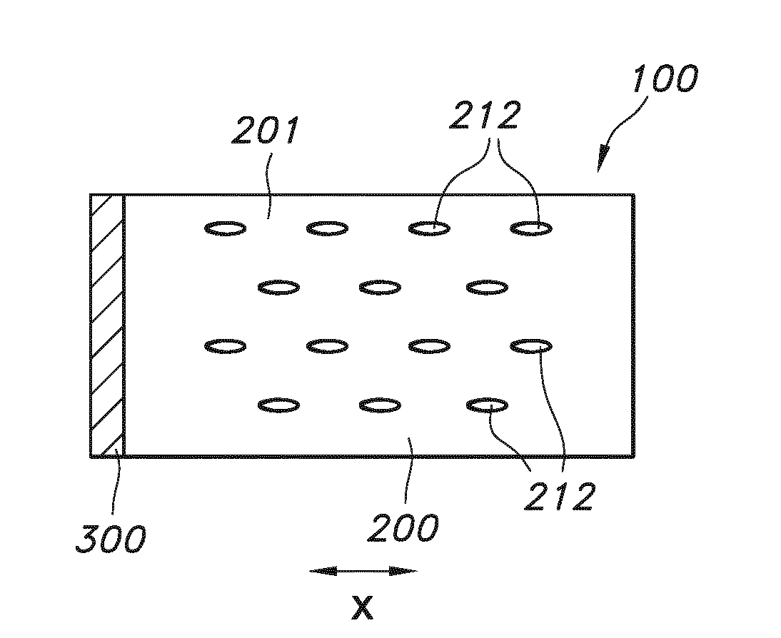
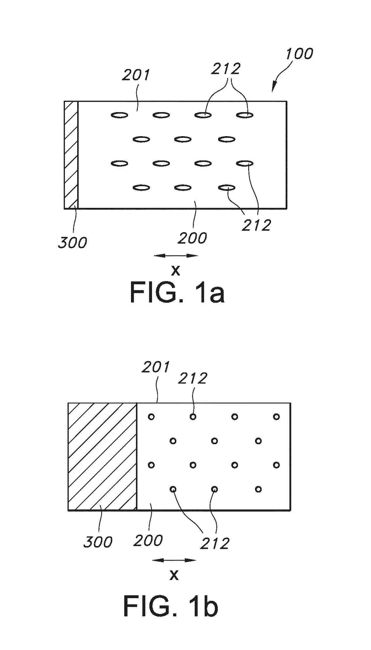
[0055]FIGS. 1a-1b very schematically depict an embodiment of the sound attenuating panel. The panel is indicated with reference 100. The sound attenuating panel 100 comprises (a) a sound attenuating unit 200 with cavities 212 with variable dimensions and (b) an infrastructure 300 for controlling the dimensions of the cavities 212 in the sound attenuating unit 200. The infrastructure can e.g. comprise an actuator configured to stretch (and / ) or press the panel material, indicated with reference 201. FIG. 1a schematically shows a stretched (or relaxed) configuration and FIG. 1b may for instance show a relaxed (or respectively pressed) configuration. The former configuration may have less sound attenuating properties, and the latter configuration, in FIG. 1b, may have better sound attenuating properties. The panel material 201 may for instance be a cellular material with holes (tunnels) cut into it. When pulled in one direction the holes will stretch and this will allow more sound to p...


PUM


Abstract

The invention provides a sound attenuating panel (100) with controllable sound attenuation properties, the sound attenuating panel (100) comprising (a) a sound attenuating unit (200) with cavities (212) with variable dimensions and (b) an infrastructure (300) for controlling the dimensions of the cavities (212) in the sound attenuating unit (200). The sound attenuating unit comprises sound attenuating material with controllable sound attenuating properties, but may also have wave guiding properties, thereby allowing to combine in the sound attenuating unit 200 both sound attenuating properties and optical properties.

Description

FIELD OF THE INVENTION[0001]The invention relates to a sound attenuating panel, to a system comprising such panel as well as to the use of such panel (and system).BACKGROUND OF THE INVENTION[0002]Acoustic panels, such as for use in work spaces, are known in the art. An example of an acoustic panel can e.g. be found in WO 2013 / 085935. This document describes a sound absorbing luminaire providing lighting for an interior space environment and managing the acoustics within the environment. The luminaire includes a frame holding an acoustic film and a lighting element, forming a resonant cavity between them. The acoustic film is used for absorbing sound within the resonant cavity, and the lighting element provides light from a light source, such as LEDs, through the acoustic film. An optical film can be mounted in the frame between the acoustic film and the lighting element for providing a desired distribution of light.SUMMARY OF THE INVENTION[0003]The office environment is changing. Ne...

Claims


Application Information

Patent Timeline
Patent Type & Authority Applications(United States)
IPC IPC(8): G10K11/172G10K11/00E04B1/82G10K11/168
CPCG10K11/172E04B1/8209G10K11/004G10K11/168E04B2/7409F21V33/006G02B6/0095G10K11/16E04B2001/8476E04B1/994E04B9/001E04B9/0464A47B97/00
Inventor MASON, JONATHAN DAVIDMEERBEEK, BERENT WILLEMBERGMAN, ANTHONIE HENDRIKKLABUNDE, KARINSARROUKH, BAHAA EDDINE
Owner SIGNIFY HLDG BV
Why Eureka
Try Eureka