Exhaust resonator for a two-stroke engine for use in a motorized float

a two-stroke engine and exhaust resonator technology, which is applied in the direction of mechanical equipment, instruments, sound producing devices, etc., can solve the problems of high total weight of the float, the design of the bent exhaust resonator requires greater strength, and the difficulty of placing this type of resonator, so as to reduce the pressure flow, the effect of reducing the energy loss and increasing the volum

Inactive Publication Date: 2016-12-29
SULA MARTIN
View PDF31 Cites 4 Cited by
  • Summary
  • Abstract
  • Description
  • Claims
  • Application Information

AI Technical Summary

Benefits of technology

[0014]Another portion through which the exhaust gases flow is the first expansion space between the stabilizer tube and the flared expansion cone. The expansion cone in combination with the stabilizer tube is used for expansion of the space in the exhaust gas flow to increase the volume, and thereby to generate the negative pressure wave. The negative pressure wave with pressure lower than outer atmospheric pressure propagates back to the engine and assists in the aspiration of more fuel mixture into the engine cylinder.
[0015]The exhaust gases impact on the secondary reflection surfaces used for the second exhaust gas flow reversing after the flow through the first expansion space. Again, these reflection surfaces have a shape that guarantee minimum energy loss in the exhaust gas reflection.
[0016]The exhaust gas flow flows through the second expansion space consisting of the outer portion of the expansion cone and the exhaust resonator wall after reflecting from the secondary reflection surfaces. Again, the combination of the two components ensures the expansion of the exhaust gas flow resulting in reducing the pressure flow.
[0017]A baffle with at least one opening is provided at the end of the second expansion space. The baffle is used to produce the overpressure wave, which returns back to the engine after the reflection, and assists in pushing the leaked fuel back to the engine cylinder. Hence, better fuel economy, lower emissions, and improved engine performance are provided. The openings in the baffle are then used for the exhaust gas to flow through the baffle to the space behind the baffle from which it then flows to the integrated noise muffler through a connection tube.
[0018]The secondary reflection surface is provided with at least one cooling opening with a nozzle used for the water supply to the first expansion space. The water supply makes cooling of the exhaust gases highly effective because the full thermal capacity of the water is used, and the water turns into steam when in contact with the exhaust gases, and the steam flows with the exhaust gases through the next portions of the exhaust system, and then out of the exhaust system. In addition, water is also injected to a place where it significantly cools the secondary reflection surface, primary reflection surface, and especially the stabilizer tube, which is subject to the exhaust gases with the highest temperature exiting directly from the engine. In addition, the injection of water directly into the exhaust gases reduces the noise emanating from both the exhaust resonator and the exhaust system as a whole. The cooling system is thereby more efficient in contrast to the standard cooling of the exhaust resonator case where the full thermal capacity of the water remains largely unused. In addition, the effective cooling of the inner, hottest portions of the exhaust resonator is impossible with the cooling of the case.
[0019]The maximum temperature occurring inside the exhaust resonator is thereby decreased significantly in the use of the effective cooling. The light metal alloys and / or composite materials may thereby be used, which results in a significant weight drop in the exhaust system and the float as a whole.

Problems solved by technology

For the use of the exhaust resonator in the motorized float with restricted spatial conditions, the placement of this type of resonator is very difficult and inconvenient.
However, the design of the bent exhaust resonator requires greater strength due to the increased stress applied to all the structural components of the exhaust resonator.
Nevertheless, these essential conditions increase the weight of the exhaust resonator, which means that total weight of the float is higher at the expense of float portability, load capacity of the float, maximum float speed, and general comfort and user experience.
In addition, a more complex design requires more demanding production technology, and the use of more expensive and specially shaped components.
Although the exhaust system has a shorter structural length compared to standard exhaust systems, it is not short enough for use in the motorized floats.
All the disadvantages mentioned above including the missing comfort and user experience, which is the basis for the use of the float, are incorporated due to the robust design and heavier weight.
Although it is claimed that the embodiment of the exhaust system substantially reduces the real length with respect to the effective length of the system, the one described therein does not provide the compactness needed for integration into the float.

Method used


Image

  • Exhaust resonator for a two-stroke engine for use in a motorized float
  • Exhaust resonator for a two-stroke engine for use in a motorized float
  • Exhaust resonator for a two-stroke engine for use in a motorized float

Examples


Embodiment Construction

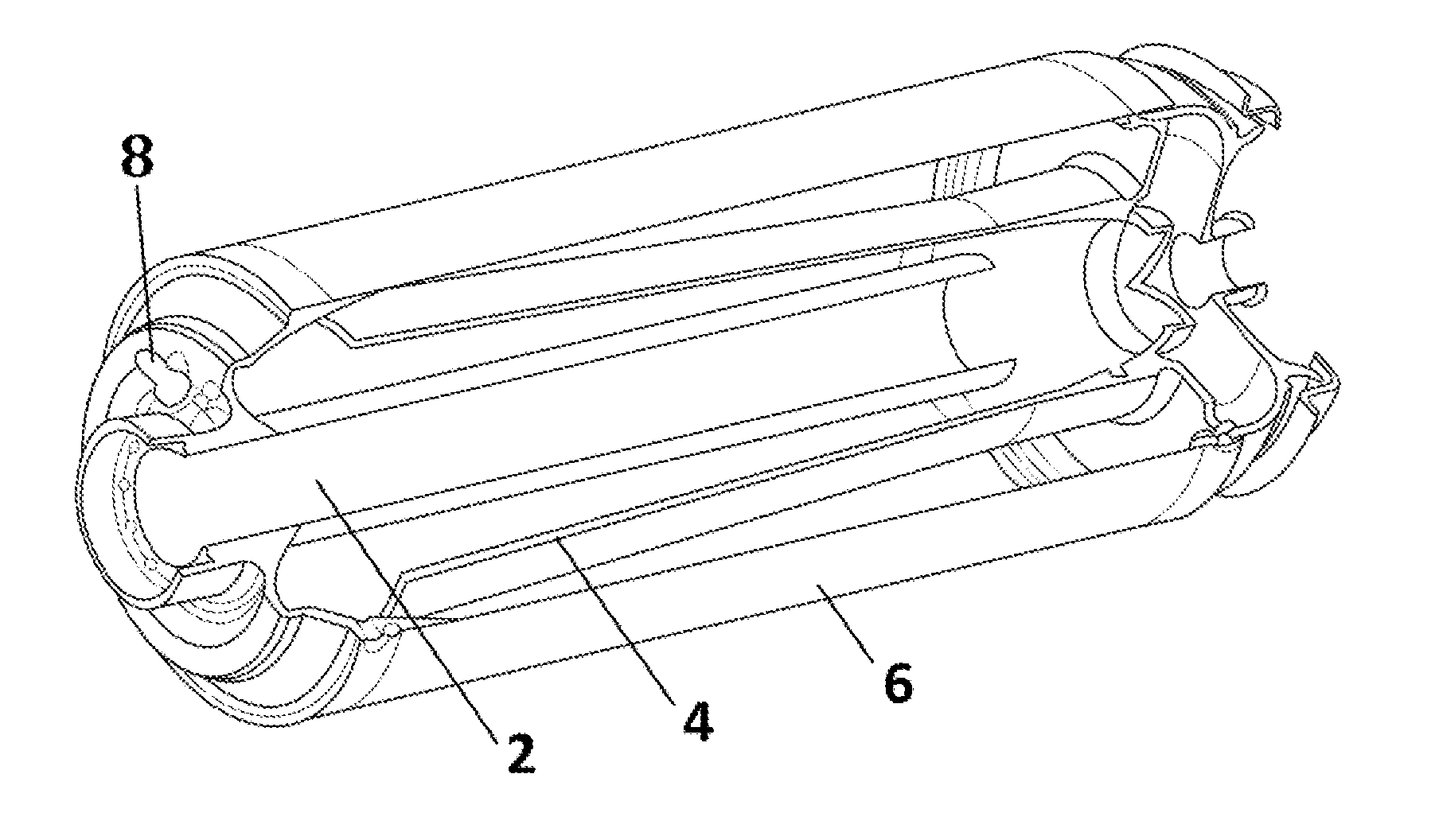
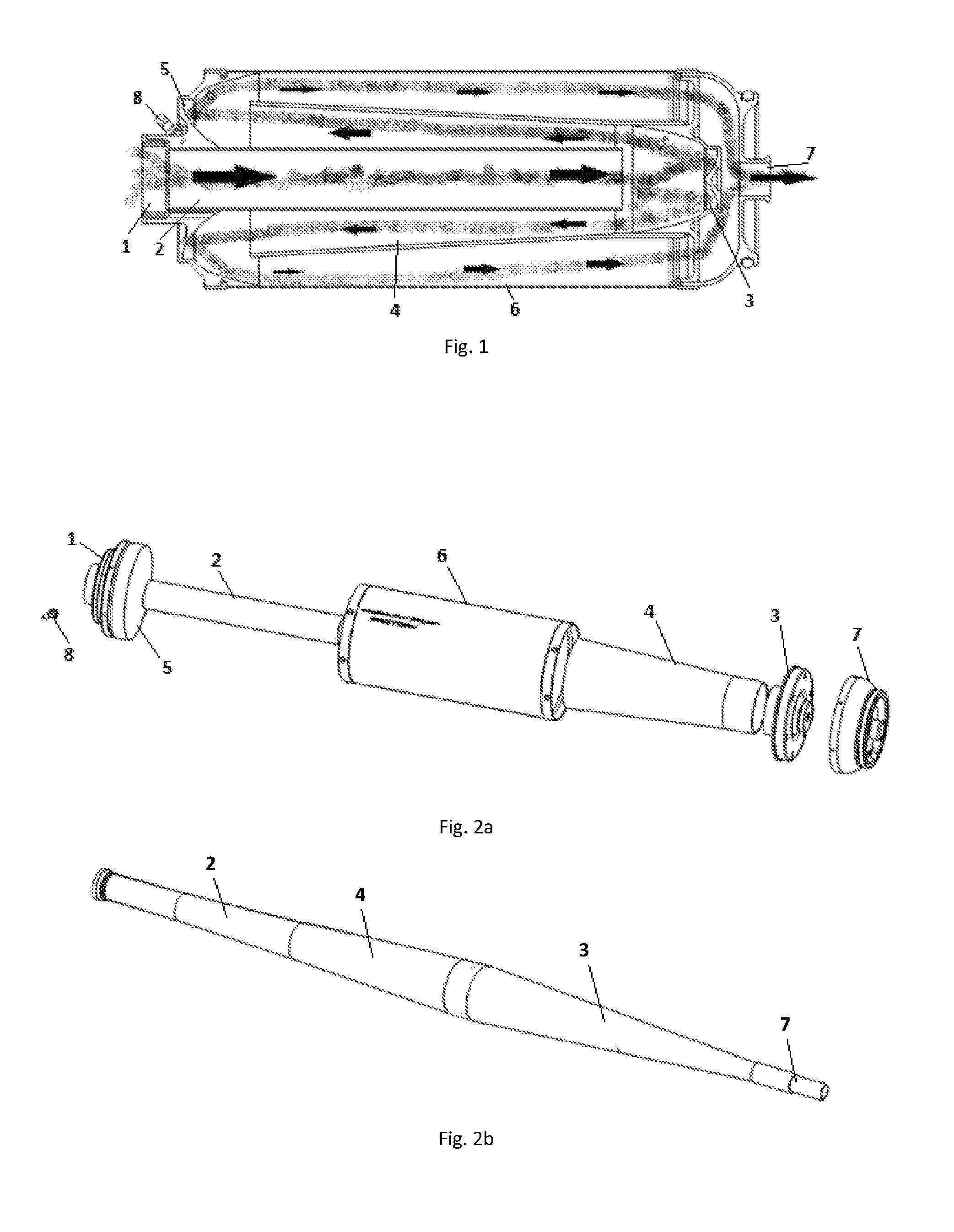
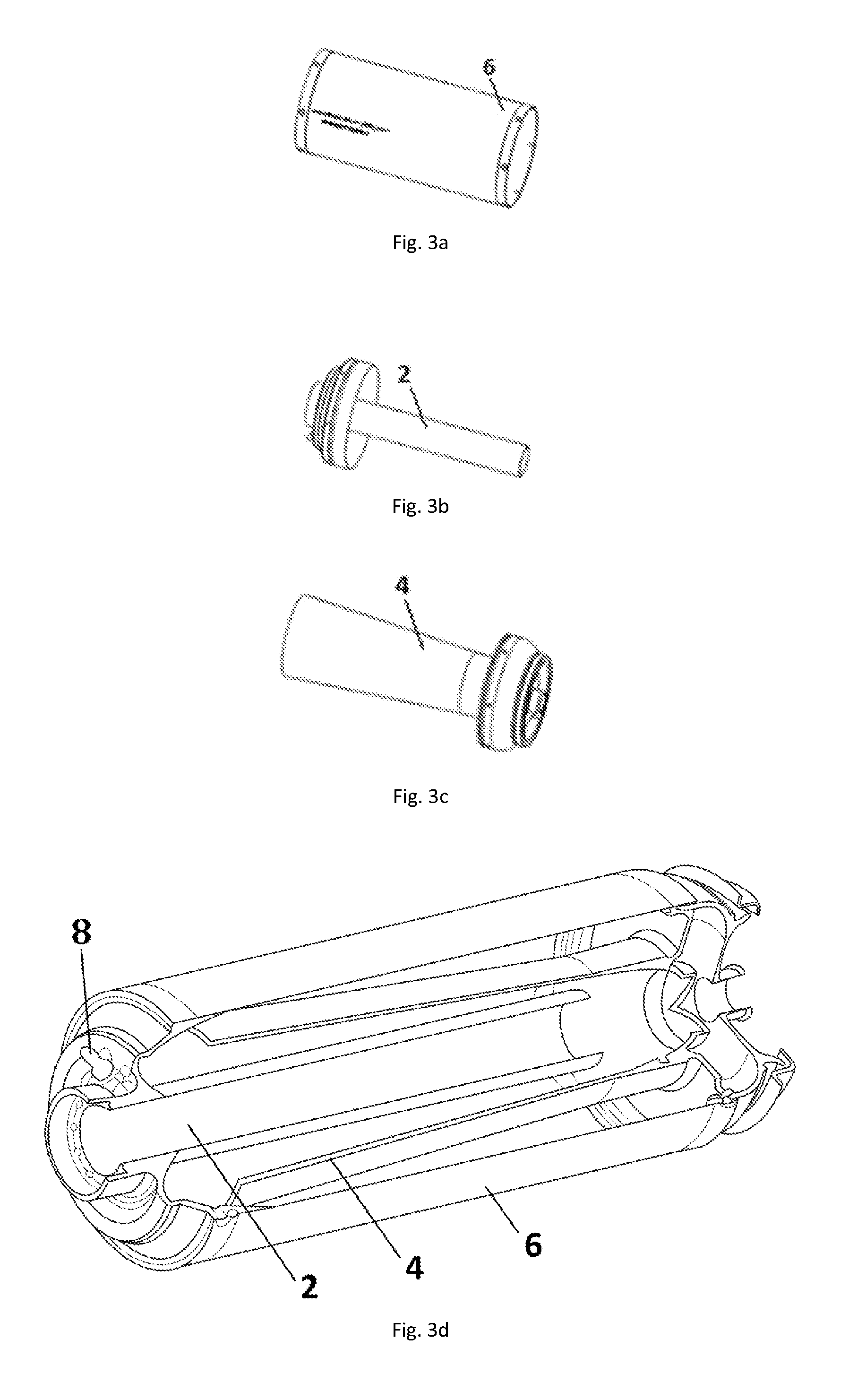
[0032]FIG. 1 illustrates a cross section of the exhaust system according to this embodiment. The inlet 1 is provided on the first cover of the exhaust resonator and the first end of the stabilizer tube 2 connects to the inlet. The stabilizer tube 2 has an elongated cylinder shaped case, and its other end is aimed at the primary reflection surface 3 arranged near the cover of the exhaust resonator. The first end of the flared expansion cone 4 surrounding the stabilizer tube 2 thus defining the first expansion space connects to the outer edges of the primary reflection surface 3 in the direction back to the first cover. The second end of the expansion cone 4 aims back at the outer edge of the first cover inwardly provided with the secondary reflection surface 5, to which the first end of the outer cylinder case 6 of the exhaust resonator surrounding the expansion cone 4 connects. The other end of the exhaust resonator case connects to the second cover of the exhaust resonator fitted w...


PUM


Abstract

An exhaust resonator comprises a first cover having an inlet. A first end of a stabilizer tube is connected to the inlet. A second end of the stabilizer tube aims at a primary reflection surface at a first end of an expansion cone surrounding the stabilizer tube to define a first expansion space. A second end of the expansion cone aims at a secondary reflection surface inwardly of a first cover. A first end of an outer case surrounds the expansion cone. A second end of the outer case connects to a second cover that is provided with the outlet. A second expansion space is defined by the expansion cone and the outer case. The second expansion space is terminated by a baffle with an opening on an interface between the outer case and the second cover. The first cover is provided with at least one coolant liquid opening.

Description

FIELD OF THE INVENTION[0001]The present invention relates to the adjustment of a tuned exhaust resonator for a two-stroke combustion engine for use in a motorized float.BACKGROUND OF THE INVENTION[0002]The exhaust systems for two-stroke engines must comply with the requirements for the appropriate characteristics of torque moment, low noise level, and reduction of exhaust emissions. In addition, the exhaust systems used in motorized floats are required to be lightweight, compact, and with a lower operating temperature compared to standard exhaust systems of that type. Therefore, the use of the correct material for production of the exhaust system is the decisive factor as well as, and particularly, the shape of the resonator design, which directly affects the pressure in the exhaust port of the engine cylinder, and therefore engine performance by proper charging, as well as the emissions of the two-stroke engine that impact the environment.[0003]Both the mass pulsation of the cylind...

Claims


Application Information

Patent Timeline
Patent Type & Authority Applications(United States)
IPC IPC(8): F01N1/08G10K11/16F02B75/02
CPCF01N1/089F02B75/02F02B2075/025G10K11/161F01N1/084F01N1/02F01N3/04G10K11/172Y02T10/12
Inventor SULA, MARTIN
Owner SULA MARTIN
Why Eureka
Try Eureka