GNSS receiver with an improved capability to resolve sub-carrier tracking ambiguities

a receiver and sub-carrier technology, applied in satellite radio beaconing, measurement devices, instruments, etc., can solve problems such as false pseudo range measurements, and higher than 9.7 ranging errors, so as to reduce receiver complexity and improve receiver robustness.

Active Publication Date: 2016-12-29
CENT NAT DETUD SPATIALES C N E S +1
View PDF2 Cites 9 Cited by
  • Summary
  • Abstract
  • Description
  • Claims
  • Application Information

AI Technical Summary

Benefits of technology

[0012]It is an object of the invention to provide improvements over the prior art. It achieves this goal by providing GNSS receiver architectures capable of delivering unbiased high precision position and time measurements from ambiguous pseudo range measurements, considering more satellites than prior art. In particular, the invention improves the receivers robustness against noise and propagation conditions, like multipath reflections or satellites masking, that are likely to happen when operating in a urban or indoor environment, and decrease the receiver complexity.

Problems solved by technology

However, a drawback of the BOC signals is that their autocorrelation function has multiple peaks and the tracking loop may therefore get locked at the correct position, on the main peak of the correlation product between the received signal and a reference signal, or at a wrong position, on a side peak of the correlation product, which creates a ranging error which can be higher than 9.7 m (case of BOC (15, 2.5)).
However, as multipath reflections might affect differently the code tracking loop and the subcarrier and code tracking loop, false readjustments of the subcarriers occur frequently in these environments, leading to false pseudo range measurements.
However, because multipath reflections significantly affect the shape of the non-ambiguous discriminator, they can preclude detection of side peak tracking, which leads to wrong pseudo range measurements.
All these techniques resolve the ambiguity problem for each satellite independently from the other satellites, therefore the ambiguity resolution does not take advantage from the other received positioning signals transmitted by the other satellites.
They can detect and exclude wrong measurements, but suffers when the input pseudo ranges match side peak tracking.
But some of these techniques do not deal with ambiguous pseudo ranges received from many satellites at the same time.
In addition their dependence on the geometry of the satellites makes them vulnerable and subject to wrong or missed satellite exclusions.
The drawbacks of the technique is the duplication of the tracking loops, two tracking loops, delivering a non-ambiguous BPSK pseudo range and an ambiguous BOC pseudo range, being necessary for each satellite.
This duplication has a cost in the receiver design, and limits the number of satellites taken in consideration for the position and time determination.
The number of tracking channels in the receiver being limited because of its direct impact on the size and power consumption of the receiver, using of the IAR technique as known from prior art, might not allow considering all in view satellites, impoverishing thus the available geometry of the satellites and therefore the navigation solution.

Method used


Image

  • GNSS receiver with an improved capability to resolve sub-carrier tracking ambiguities
  • GNSS receiver with an improved capability to resolve sub-carrier tracking ambiguities
  • GNSS receiver with an improved capability to resolve sub-carrier tracking ambiguities

Examples


Embodiment Construction

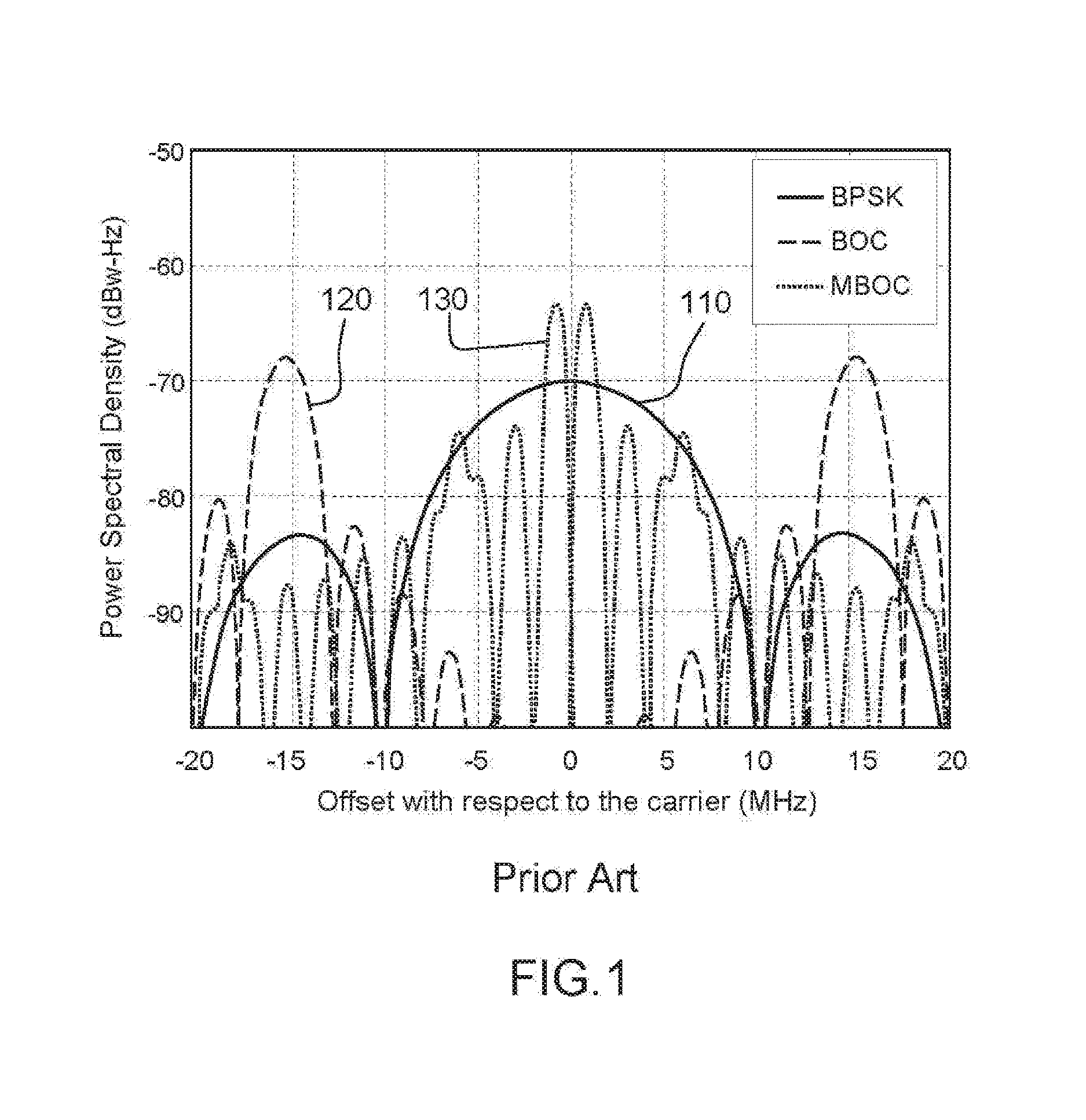
[0061]FIG. 1 represent exemplary spectrums of a BPSK (110), a BOC (120), and a MBOC (130) signal, according to the prior art.

[0062]In FIG. 1, spectrums are represented with respect to the carrier frequency. It can be observed that the BPSK spectrum 110 is centered on the carrier frequency.

[0063]Generating a BOC signal comprises modulating the carrier of the signal by a code and a subcarrier. BOC modulation is usually described as:

x(t)=√{square root over (A)}·d(t)·c(t)·s(t)·exp(j[2πfct+θ])

where √{square root over (A)} is the complex signal's amplitude, d(t) the data transmitted (if any), c(t) the pseudo-random noise (PRN) code signal, s(t) the subcarrier signal, fc and θ the carrier frequency and phase.

[0064]As a consequence of the modulation by the subcarrier signal, the BOC spectrum 120 is split in two side bands distributed on either side of the nominal carrier frequency, with a frequency shift equivalent to the subcarrier frequency. Each lobe of the signal can be seen as a BPSK s...


PUM


Abstract

A GNSS receiver and the associated method, for calculating an unbiased position and time measurement from a plurality of satellite positioning signals, the receiver comprising:
    • a plurality of circuits configured to receive positioning signals from a plurality of satellites in GNSS constellations,
    • a plurality of first and second signal processing channels configured for processing a first selection of said positioning signals and determining associated first pseudo ranges,
    • a computer logic,
  • wherein:
    • the computer logic is configured to calculate the unbiased position and time measurement from pseudo ranges being determined from positioning signals originating from distinct satellites.
A GNSS receiver further comprising a second computer logic configured to calculate a second unbiased position and time from the first position and time, and the second signal processing signals.

Description

FIELD OF THE INVENTION[0001]The present invention applies to the field of satellite navigation. More specifically, the invention allows a satellite navigation receiver to acquire and track signals with multiple autocorrelation peaks.BACKGROUND[0002]There are two Global Navigation Satellite Systems (GNSS) which have been fully deployed for a number of years (the US Global Positioning System, the Russian GLONASS) and two more which are under deployment (the Chinese Beidou Navigation Satellite System and the European Galileo system). These systems rely on the same principles: microwave radio signals are broadcast from a number of satellites which orbit in a non-geostationary orbit; the signals carry a PRN (Pseudo Random Noise) code which is correlated with a local replica in a receiver configured to receive the broadcast signals; when a receiver is capable of acquiring and tracking signals from a satellite, its processing capabilities demodulate the code signal using the correlation pr...

Claims


Application Information

Patent Timeline
Patent Type & Authority Applications(United States)
IPC IPC(8): G01S19/29G01S19/44
CPCG01S19/44G01S19/29G01S19/37G01S19/49G01S19/30G01S19/32G01S19/33G01S19/31G01S19/28G01S19/38G01S19/22
Inventor JARDAK, NABILVIGNEAU, WILLYMARMET, FRANCOIS-XAVIERRIES, LIONEL
Owner CENT NAT DETUD SPATIALES C N E S
Why Eureka
Try Eureka