
Polarizer and polarizing plate including same

a technology of polarizer and polarizing plate, which is applied in the direction of polarizing elements, instruments, optics, etc., can solve the problems of insufficient measurement of above methods, insufficient addition of zinc ions, and easy red discoloration of polarizers with a small thickness

Active Publication Date: 2016-12-29
SUMITOMO CHEM CO LTD
View PDF7 Cites 3 Cited by
  • Summary
  • Abstract
  • Description
  • Claims
  • Application Information

AI Technical Summary

Benefits of technology

The invention's polarizer and polarizing plate can resist red discoloration and maintain a neutral display even if the polarizer is as thin as 10 μm. This means that the invention can maintain its display quality even at high temperatures.

Problems solved by technology

However, red discoloration can easily occur particularly in a polarizer with a small thickness because water can come in and go out of such a polarizer significantly faster than in and out of a normal polarizer.
The above methods are not considered to be sufficient measures to suppress the red discoloration of such a polarizer.
In addition, the method of adding zinc ions raises other problems such as irritation to skin, environmental impact of waste water, and precipitation of zinc on the surface of a polarizer.
Even when the above-mentioned measures effective for a thick polarizer with a thickness greater than or equal to 20 μm are performed on a polarizer with a thickness less than or equal to 10 μm, red discoloration can locally occur to produce unevenness, and in some cases, a problem can occur in that an unnecessarily bad looking polarizing plate is formed.

Method used

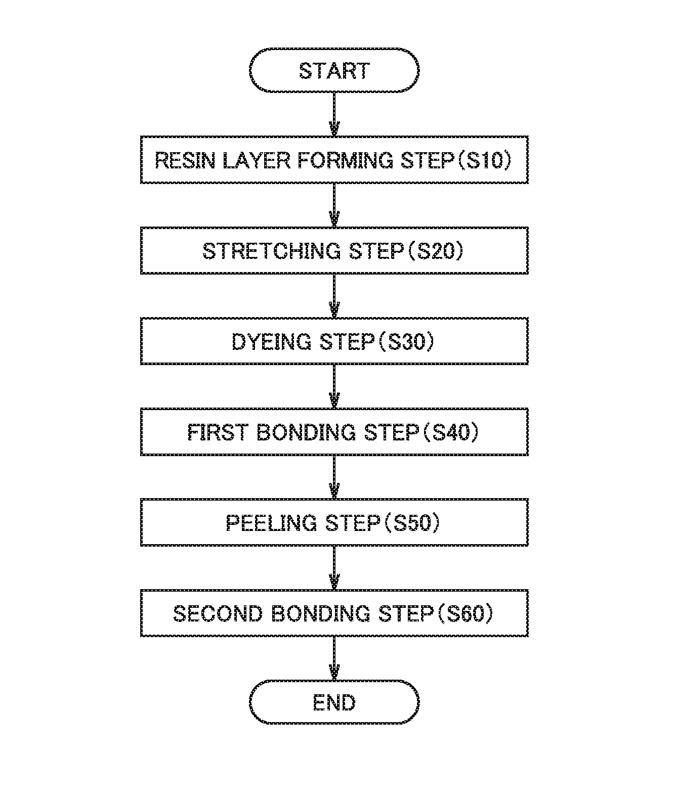
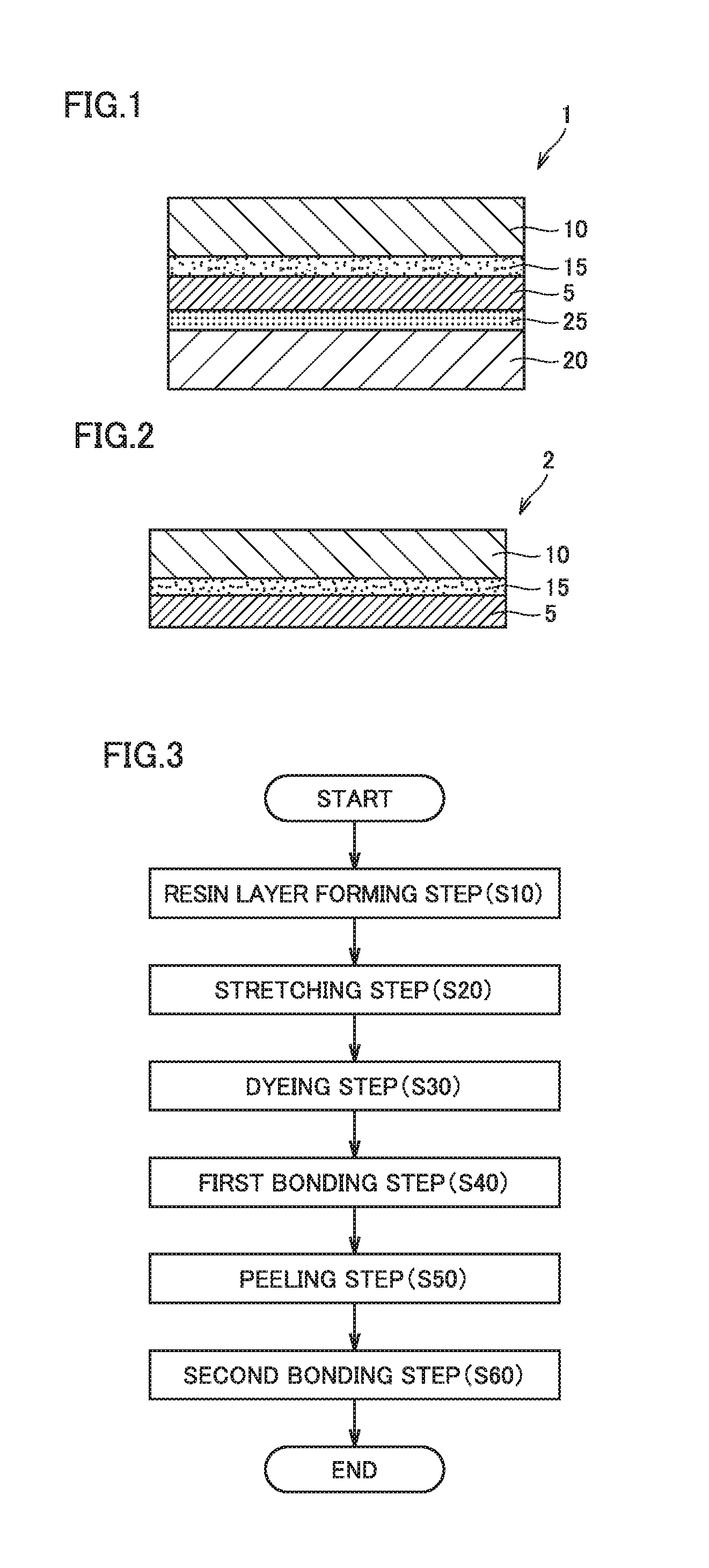
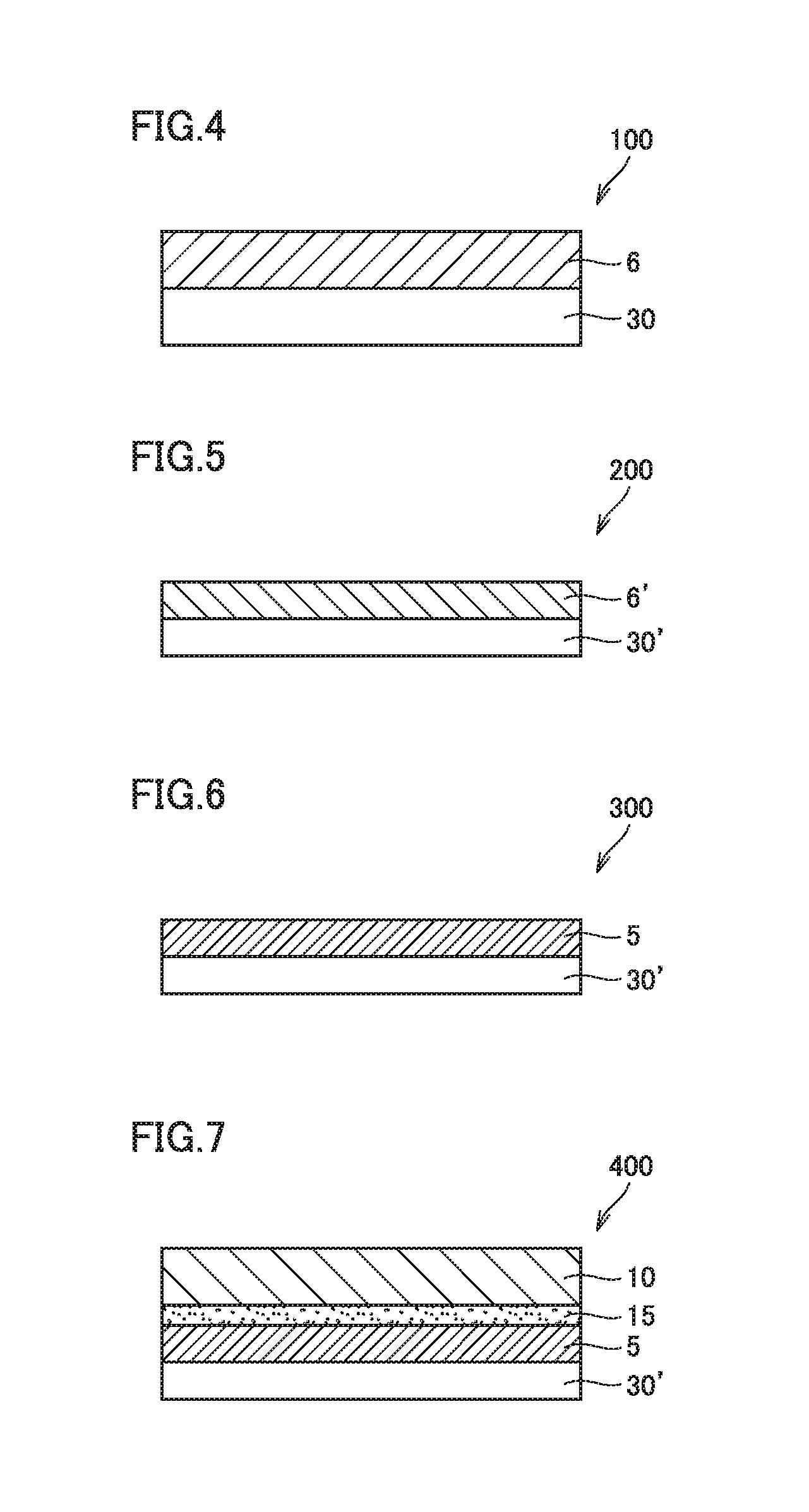

Image

  • Polarizer and polarizing plate including same
  • Polarizer and polarizing plate including same
  • Polarizer and polarizing plate including same

Examples


example 1

(1) Primer Layer Forming Step

[0207]First, a 90-μm-thick unstretched polypropylene (PP) film (melting point: 163° C.) was provided as a substrate film. The substrate film had a tensile elasticity of 220 MPa at 80° C. The substrate film also had a thickness distribution of 3.0 μm / 10 mm in the widthwise direction.

[0208]Next, a polyvinyl alcohol powder (Z-200 manufactured by The Nippon Synthetic Chemical Industry Co., Ltd., 1,100 in average polymerization degree, 99.5 mol % in saponification degree) was dissolved in hot water at 95° C. to form a 3% by weight polyvinyl alcohol aqueous solution. A primer layer-forming coating liquid was obtained by mixing the resulting aqueous solution and a cross-linking agent (Sumirez Resin 650 manufactured by Taoka Chemical Co., Ltd.) in such a way that the weight ratio of the crosslinking agent to the polyvinyl alcohol powder was 5 to 6.

[0209]After one surface of the substrate film was subjected to a corona treatment, the primer layer-forming coating ...

example 2

[0219]A double side protective films-bearing polarizing plate was prepared in the same manner as in Example 1, except that a substrate film with an elasticity of 240 MPa was used instead. The polyvinyl alcohol-based resin layer had a thickness distribution of 0.5 μm / 10 mm in the widthwise direction.

example 3

[0220]A double side protective films-bearing polarizing plate was prepared in the same manner as in Example 1, except that after the polyvinyl alcohol-based resin layer-forming coating liquid was applied, the drying was performed using a floating-type drying furnace while end parts of the film were pinched with pinch rolls. The polyvinyl alcohol-based resin layer had a thickness distribution of 0.5 μm / 10 mm in the widthwise direction.


PUM

PropertyMeasurementUnit
thicknessaaaaaaaaaa
heat resistance testaaaaaaaaaa
thicknessaaaaaaaaaa

Abstract

Provided are a polarizer that resists red discoloration in a heat resistance test even when it has a small thickness, and a polarizing plate including the polarizer. The polarizer has a thickness less than or equal to 10 μm and an Rpva variation within 0.2 nm / mm in the transmission axis direction.

Description

TECHNICAL FIELD[0001]The invention relates to a polarizer and a polarizing plate including the same.BACKGROUND ART[0002]Polarizing plates are widely used in displays such as liquid crystal displays and, particularly in recent years, in a variety of mobile devices such as smart phones and slate PCs. For use in mobile devices, polarizing plates are increasingly required to be thin and light. On the other hand, polarizing plates are also required to have high heat resistance.[0003]However, conventional polarizing plates can cause a problem called “red discoloration”, in which light in the red region leaks from polarizing plates having undergone a heat resistance test (generally at 80 to 85° C. for 500 to 750 hours). Various methods have been proposed to suppress discoloration such as red discoloration.[0004]Conventional methods for suppressing discoloration or decoloration of polarizers include, for example, a method of adding sulfate ions to polarizers (PTD 1); a method in which a pro...

Claims


Application Information

Patent Timeline
Patent Type & Authority Applications(United States)
IPC IPC(8): G02B5/30G02B1/14G02B1/08
CPCG02B5/3033G02B1/14G02B1/08G02B5/305
Inventor KUNAI, YUICHIRO
Owner SUMITOMO CHEM CO LTD
Learn More