Bifocal lens and imaging device including same

a technology of bifocal lens and imaging device, applied in the field of dual-focus lenses, can solve the problems of long and heavy cameras, difficult to capture images with various photography effects by using single-focus lenses, and long-focus lenses for long-range photography, etc., and achieve the effect of thinly manufactured

Inactive Publication Date: 2016-12-29
SAMSUNG ELECTRONICS CO LTD
View PDF11 Cites 7 Cited by
  • Summary
  • Abstract
  • Description
  • Claims
  • Application Information

AI Technical Summary

Benefits of technology

[0036]A dual focus lens according to the disclosed embodiments may include a refractive optical system including at least one refractive lens element and a reflective optical system including a plurality of reflection surfaces. Since the refractive optical system and the reflective optical system have different focal lengths, the dual focus lens of the present embodiments may be capable of both short distance and long distance photography. For example, the refractive optical system having a short focal length may be used for short distance photography, and the reflective optical system having a long focal length may be used for long distance photography.
[0037]Also, the reflective optical system may have a folded optics structure in which a light path bends a plurality of times between the reflection surfaces, and thus be short in a direction of an optical axis. Therefore, the dual focus lens according to the present embodiments may have two different focal lengths and also be thinly manufactured.
[0038]Furthermore, since the refractive optical system and the reflective optical system are located having a common optical axis in the center and image planes thereof are located at a substantially identical location, an image pickup device including the dual focus lens according to the present embodiments may use only one image sensor.

Problems solved by technology

However, since the single focus lenses have fixed viewing angles, it is difficult to capture images with various photography effects by using the single focus lenses.
In particular, the compact cameras and the cameras in the mobile devices are mostly designed to be appropriate for short distance photography, but not for long distance photography.
However, the zoom lens used in the compact cameras usually includes at least six lenses, thereby causing cameras to be long and heavy.
Although the mirrorless cameras and the single-lens reflex cameras may be used by changing various single focus lenses having different focal lengths, there are still problems in that long focus lenses for long distance photography are long and large, and there are also inconveniences of having to change lenses.
Furthermore, since the cameras in the mobile devices are relatively small, it is difficult to apply the zoom lens in the cameras in the mobile devices.
Even when an additional lens may be externally attached to a camera in a mobile device by using an adapter so as to perform long distance photography, the camera in the mobile device may increase in size.
However, such lenses require two image sensors, thereby causing an increase in a manufacturing cost and a size of a camera.

Method used


Image

  • Bifocal lens and imaging device including same
  • Bifocal lens and imaging device including same
  • Bifocal lens and imaging device including same

Examples


first embodiment

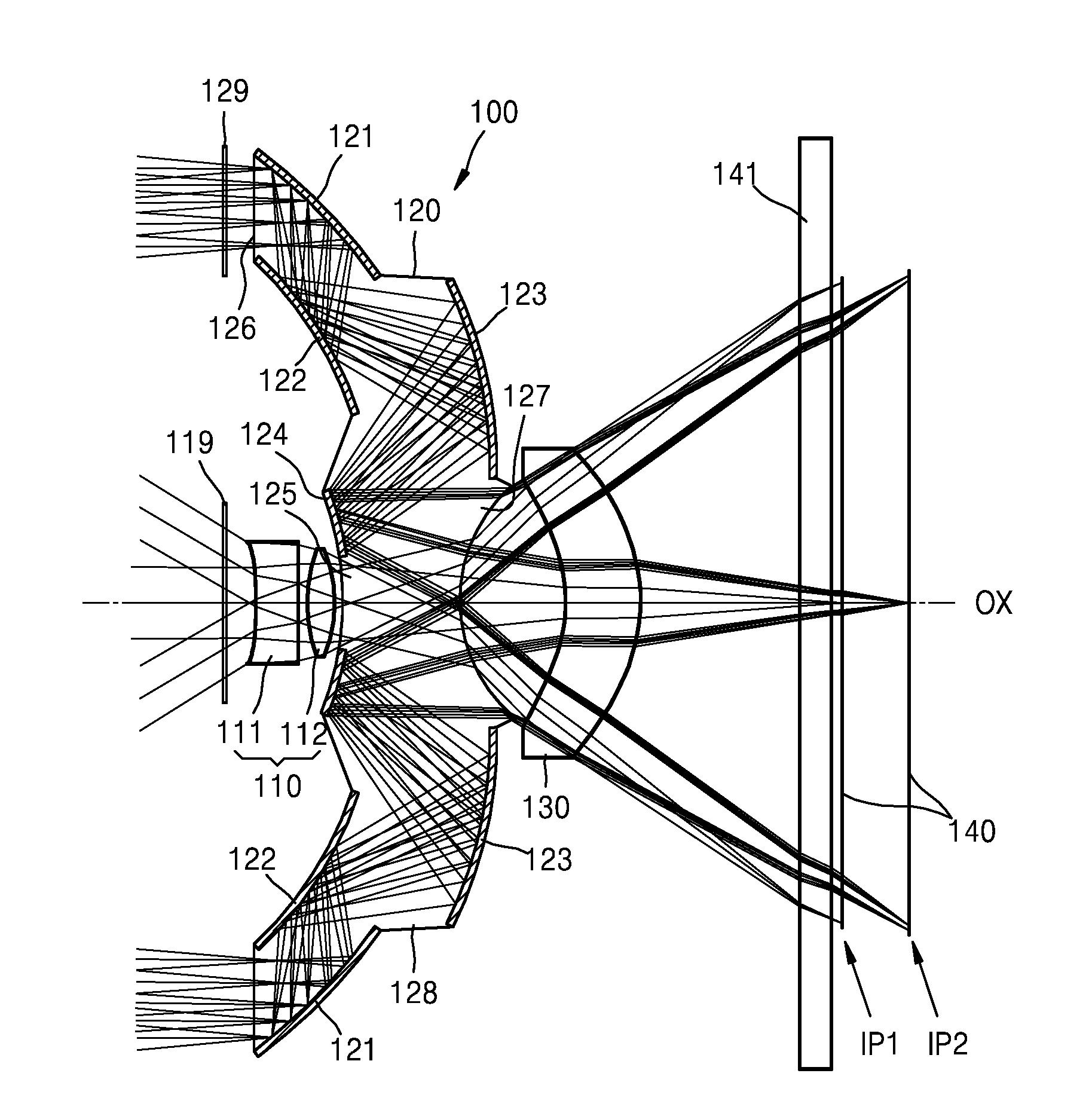
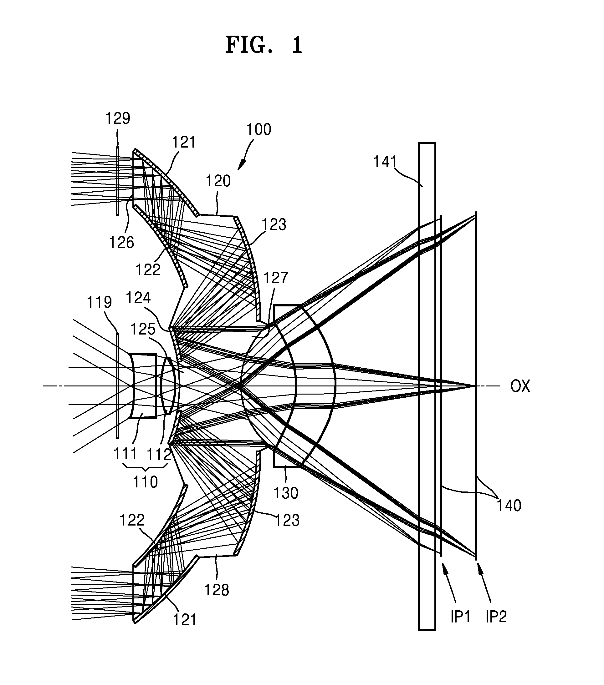
[0094]The dual focus lens 100 having the structure illustrated in FIG. 1 is manufactured according to a first embodiment. FIG. 12 is a table of specific optical data of the refractive optical system 110 of the dual focus lens 100, according to the first embodiment. In FIG. 12, surfaces S0 and S1 indicate both surfaces of the first shutter 119. Surfaces S2 to S12 are shown in FIG. 6. For example, the surfaces S2 and S3 indicate both surfaces of the first refractive lens element 111, the surfaces S4 and S5 indicate both surfaces of the second refractive lens element 112, the surfaces S6 and S7 respectively indicate the first light incident region 125 and the light emission region 127, the surfaces S8 and S9 indicate both surfaces of the common lens element 130, the surfaces S10 and S11 indicate both surfaces of the cover layer 141, and the surface S12 indicate a surface of the image sensor 140.

[0095]As shown in FIG. 12, the first refractive lens element 111 is a meniscus lens having a...

second embodiment

[0102]FIG. 17 is a schematic cross-sectional view of a dual focus lens 300, according to a second embodiment. The dual focus lens 300 according to the second embodiment includes the refractive optical system 110 having a first focal length, the reflective optical system 120 having a second focal length that is different from the first focal length, and first to third common lens elements 131, 132, and 133. Difference between the first and second embodiments is in that the dual focus lens 300 according to the second embodiment includes the first to third common lens elements 131, 132, and 133, and image planes of the refractive and reflective optical systems 110 and 120 are the same.

[0103]FIG. 18 is a cross-sectional view of the refractive optical system 110 of the dual focus lens 300, according to the second embodiment. FIG. 19 is a table of specific optical data of the refractive optical system 110 of the dual focus lens 300, according to the second embodiment. In the table of FIG....


PUM


Abstract

Disclosed are a bifocal lens having two focal distances to enable near image capturing and far image capturing and capable of being manufactured to have a thin profile, and an imaging device including same. A bifocal lens according to disclosed embodiments may include: a refractive optical system having at least one refractive lens element and having a first focal distance; and a reflective optical system having multiple reflective surfaces and having a second focal distance that is different from the first focal distance. Because the refractive optical system and the reflective optical system have mutually different focal distances, the bifocal lens according to an embodiment may be capable of both near image capturing and far image capturing.

Description

TECHNICAL FIELD[0001]One or more embodiments of the present disclosure relate to a dual focus lens having two focal lengths and an image pickup apparatus including the dual focus lens, and more particularly, to a dual focus lens which may be thinly manufactured having two focal lengths for short distance and long distance photography, and an image pickup apparatus including the dual focus lens.BACKGROUND ART[0002]Due to a recent trend in reducing sizes of not only compact cameras and cameras in mobile devices, but also sizes of mirrorless cameras and single-lens reflex cameras, there is a demand for the development of small camera lenses. In general, the small camera lenses are designed as single focus lenses. However, since the single focus lenses have fixed viewing angles, it is difficult to capture images with various photography effects by using the single focus lenses. In particular, the compact cameras and the cameras in the mobile devices are mostly designed to be appropriate...

Claims


Application Information

Patent Timeline
Patent Type & Authority Applications(United States)
IPC IPC(8): G02B13/00H04N5/225G02B27/14G02B3/10G02B17/08
CPCG02B13/0065G02B3/10G02B17/084G02B27/141H04N5/2259H04N5/2254G02B13/009G02B15/14G02B17/08G02B3/0087G03B17/12G02B2003/0093H04N23/55
Inventor CHOI, JONG-CHULLEE, JIN-WONCHUNG, CHONG-SAM
Owner SAMSUNG ELECTRONICS CO LTD
Why Eureka
Try Eureka