Railway wheel with brake disc

Inactive Publication Date: 2017-01-12
NIPPON STEEL & SUMITOMO METAL CORP
View PDF7 Cites 0 Cited by
  • Summary
  • Abstract
  • Description
  • Claims
  • Application Information

AI Technical Summary

Benefits of technology

[0023]The aerodynamic sound during high speed traveling is suppressed, and besides, the brake disc has a simple shape and an

Problems solved by technology

Such a gas flow becomes significant when the vehicle travels at a high speed of more than 300 km/h, like a high-speed railway vehicle such as the Shinkansen (R), thereby inducing noise of wind noise.
Therefore, it can be said that the generation of aerodynamic sound is a problem peculiar to the center-fastening type brake disc.
However, in the technique disclosed in Patent Literature 2, cooling performance for th

Method used


Image

  • Railway wheel with brake disc
  • Railway wheel with brake disc
  • Railway wheel with brake disc

Examples


Example

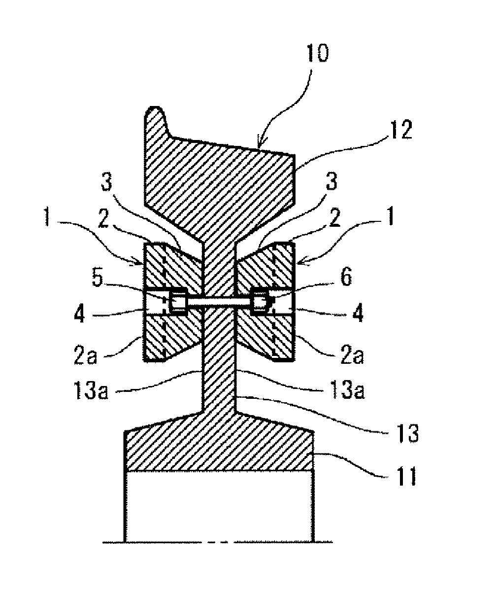
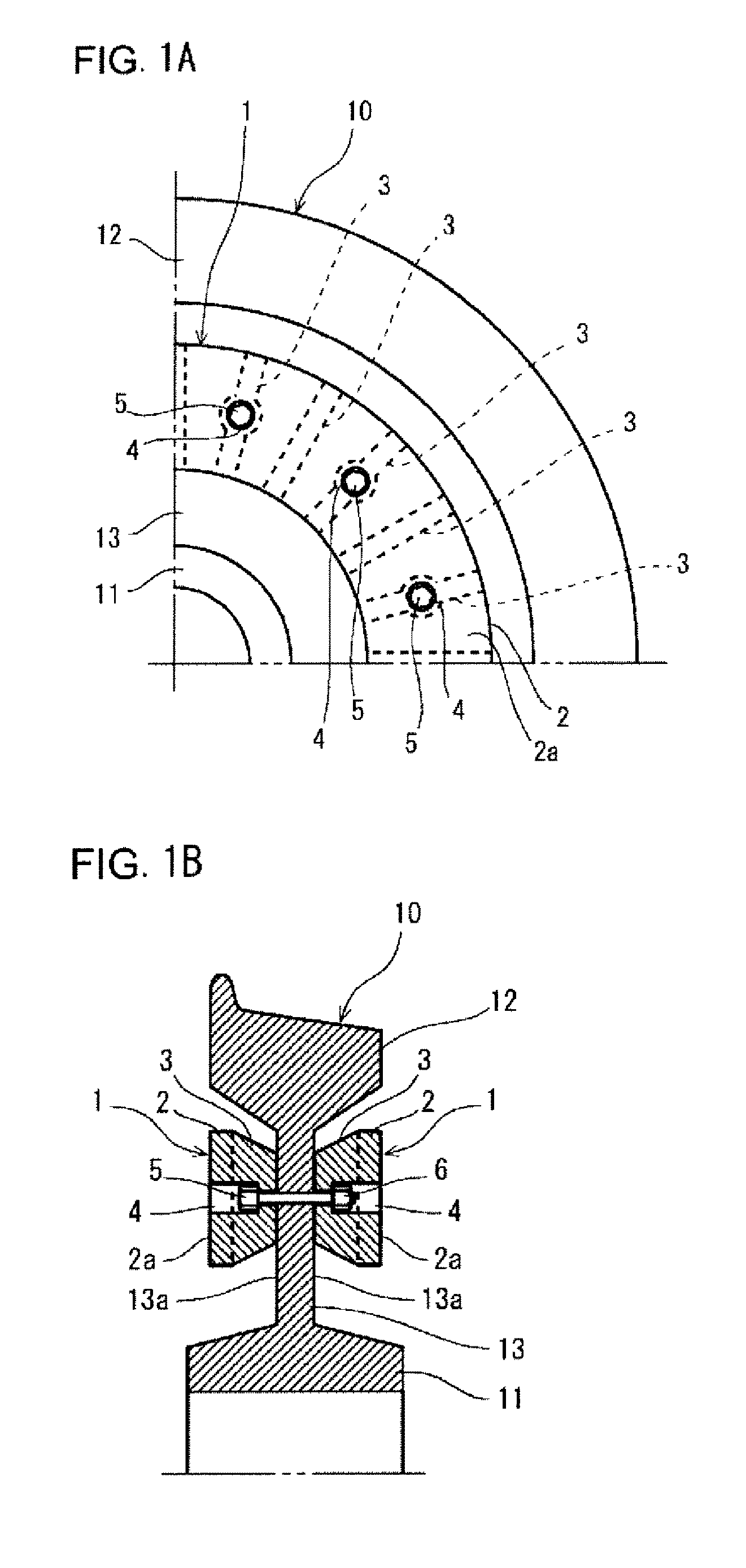
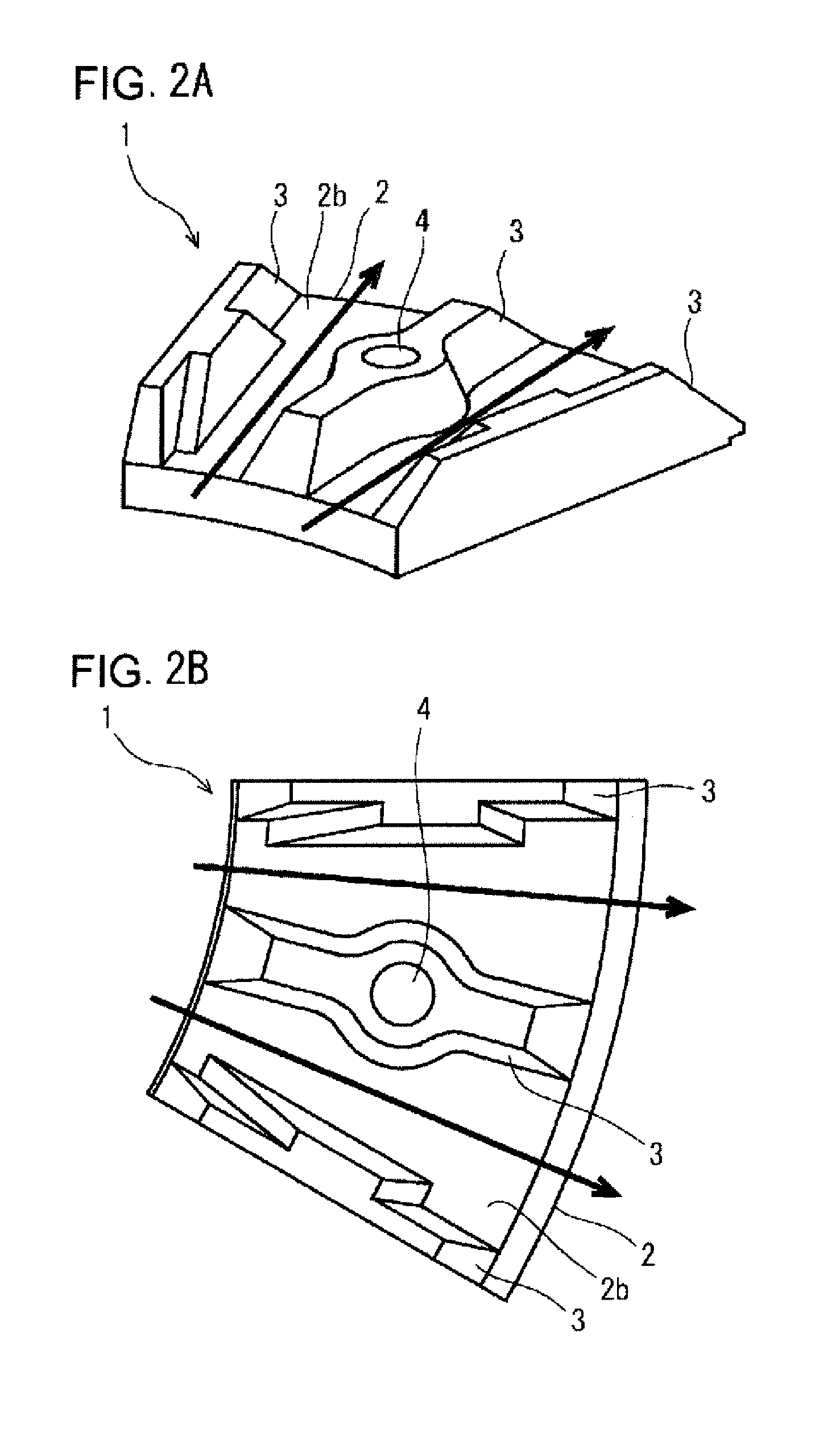
[0048]As described in Patent Literature 3, there is a strong correlation between the ventilation amount of the air, which flows through a space formed between the brake disc and the wheel, particularly, a space surrounded by the circular plate portion and the fin portion of the brake disc and the plate portion of the wheel, and the level of aerodynamic sound.

[0049]FIG. 4 is a diagram to show a correlation between the sum total of opening areas, and the aerodynamic sound level and the ventilation amount in the railway wheel with brake disc. The sum total of opening areas mentioned herein refers to a sum total of opening areas over the entire range of the circumferential direction when seen from the inner circumferential side of the brake disc regarding a space surrounded by the circular plate portion and the fin portion of the brake disc, and the plate portion of the wheel. In other words, the sum total of opening areas refers to an area of a minimum section portion in which area of ...


PUM


Abstract

A railway wheel includes: a wheel including a plate portion; and a brake disc including a circular plate portion whose front face side is a sliding surface, and a plurality of fin portions projected on a back face of the circular plate portion, wherein two of the brake discs are fastened in a region within the sliding surface. Regarding an area of a section crossing a space formed between the brake disc and the wheel along a circumferential direction, a minimum section portion in which the sectional area is minimum is present closest to the back face within the outer peripheral surface of the circular plate portion within a region formed by an outer peripheral surface of the circular plate portion and an inner peripheral surface of the rim portion, and an area of the minimum section portion is not less than 2500 mm2 and not more than 7000 mm2.

Description

TECHNICAL FIELD[0001]The present invention relates to a railway wheel with brake disc (hereafter, also referred to simply as a “railway wheel with BD”), in which brake discs are fastened to a wheel for a railway vehicle.BACKGROUND ART[0002]As a braking system for railway vehicles, disc brakes which have excellent braking performance become more frequently used as the speed of vehicle and the size thereof increase. A disc brake is configured such that a brake lining is pressed against a sliding surface of a brake disc attached to a wheel. As a result, braking force is generated in a rotating wheel, thereby controlling the speed of vehicle.[0003]The type of disc brake includes a center-fastening type (sliding-surface fastening type) brake disc in which brake discs are fastened to a wheel in a region within a sliding surface, and an inner-circumference fastening type brake disc in which brake discs are fastened to a wheel in a region located closer to the inner circumference than the s...

Claims


Application Information

Patent Timeline
IPC IPC(8): B60B17/00
CPCB60B17/0006F16D65/122F16D65/128F16D2069/005F16D65/0006F16D65/12F16D2065/138B61F13/00B61H5/00
Inventor SAKAYAMA, YUIKONOGAMI, HIROSHIFUJIMOTO, TAKAHIROSAKAGUCHI, ATSUSHIASABE, KAZUTAKA
Owner NIPPON STEEL & SUMITOMO METAL CORP
Why Eureka
Try Eureka