
Pneumatic Tire

Active Publication Date: 2017-01-12
YOKOHAMA RUBBER CO LTD
View PDF6 Cites 3 Cited by
  • Summary
  • Abstract
  • Description
  • Claims
  • Application Information

AI Technical Summary

Benefits of technology

The technology in this patent provides a tire with a special sound-absorbing member on the inside that can help reduce noise and provide better durability. It also helps reduce strain on the tire's surface and prevents the sound-absorbing member from peeling off during high-speed travel.

Problems solved by technology

In pneumatic tires, cavernous resonance caused by the vibration of air that the tire is filled with is one cause of noise being generated.
When a tire is rolled, uneven treading surfaces cause a tread portion to vibrate.
However, radial growth is produced by centrifugal force during high-speed traveling, so this produces a shear strain in the bonding surface of the sound-absorbing member.
Then after the bonding surface of the sound-absorbing member that is bonded to the tire inner surface has been subjected to shear strain repetitively over a long period of time, the problem of peeling of the sound-absorbing member from the tire inner surface can occur.
However, although nylon fiber cords are excellent from the cost point of view, they cannot necessarily sufficiently withstand the shear strain of the tire inner surface produced by centrifugal force during high-speed traveling, so at present they are unable to reduce peeling of the sound-absorbing member.
High angle belt layers are frequently adopted in order to ensure steering performance in high performance tires for which high-speed traveling is envisaged, but when the cord angle of the belt layers is increased, the radius of curvature on the tire inner surface in a tire meridian cross-section becomes smaller, which causes strain in the bonding surface of the sound-absorbing member.

Method used


Image

  • Pneumatic Tire
  • Pneumatic Tire
  • Pneumatic Tire

Examples


examples

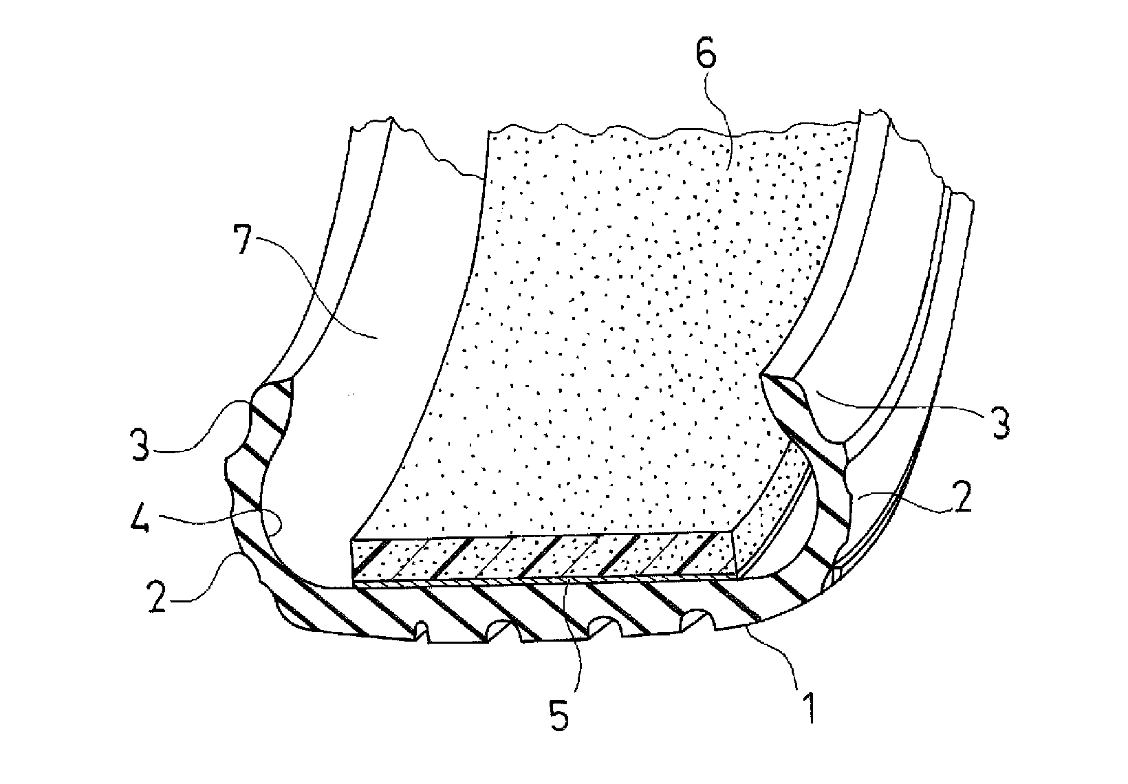
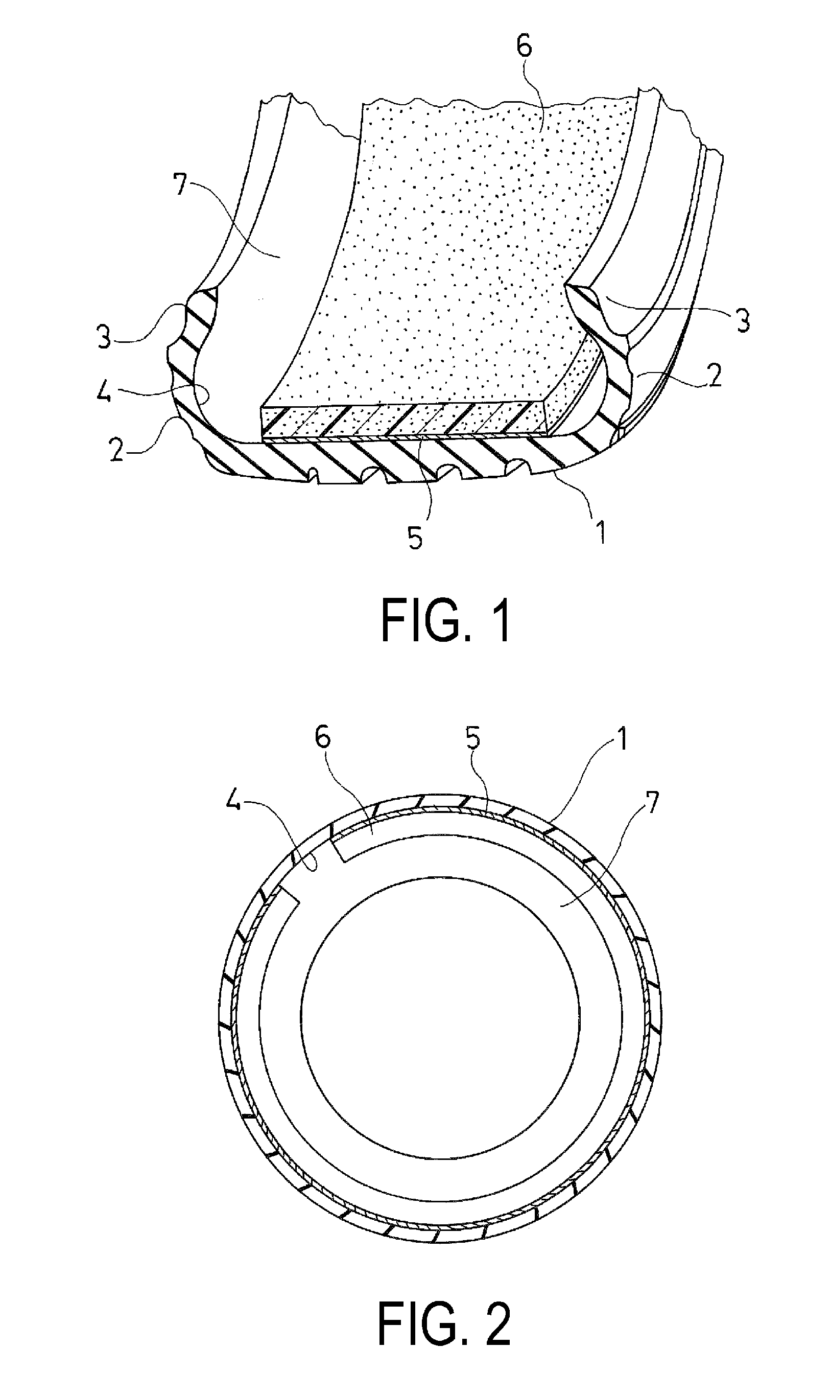
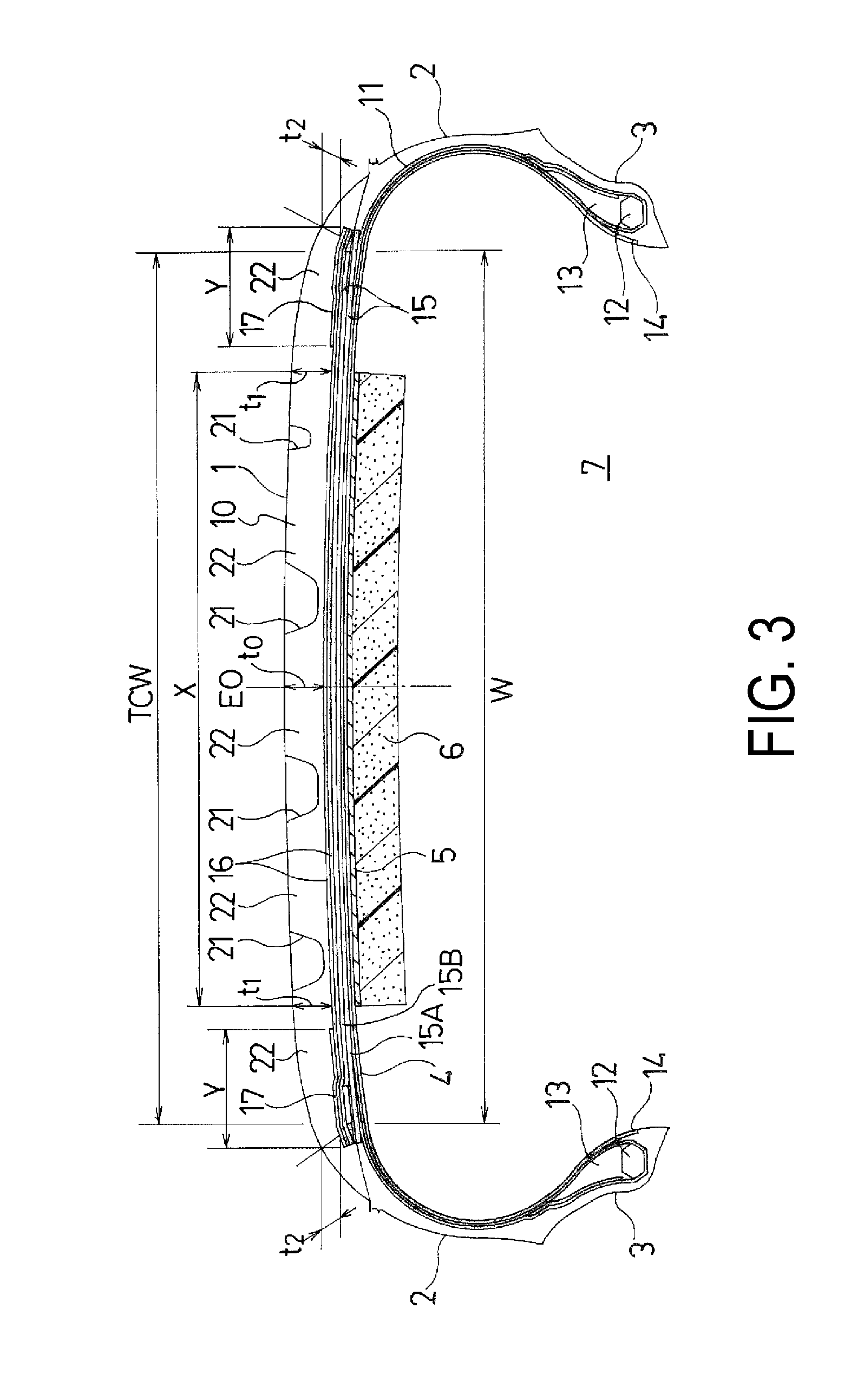
[0054]Pneumatic tires according to Comparative Examples 1 to 3 and Working Examples 1 to 4 were manufactured to a tire size 275 / 35R20, having an annular tread portion extending in the tire circumferential direction, a pair of sidewall portions disposed on the two sides of the tread portion, and a pair of bead portions on the inner side in the tire radial direction of the sidewall portions. A strip-shaped sound-absorbing member was bonded to the region of the tire inner surface corresponding to the tread portion along the tire circumferential direction. A carcass layer was mounted between the pair of bead portions, and two layers of belt layers were disposed on the outer circumferential side of the carcass layer in the tread portion. A belt cover layer made from aliphatic polyamide fiber cords oriented in the tire circumferential direction was disposed on the outer circumferential side of the belt layers and extending over the whole width of the belt layers. A belt edge cover layer m...


PUM


Abstract

The present technology provides a pneumatic tire having a strip-shaped sound-absorbing member bonded on the inner surface of the tire includes a plurality of belt layers, two or more belt cover layers, one or more belt edge cover layers, and a thread rubber layer. The thickness of the tread rubber layer is substantially uniform in the region X where the sound-absorbing member is located so that the difference between the thickness t1 at an end of the sound-absorbing member and the thickness t0 at the position of the tire equator is equal to or less than 0.5 mm. The thickness of the tread rubber layer is smaller in the region Y where the belt edge cover layer is located than in the region X so that the difference between the minimum value t2 of the thickness in the region Y and the thickness t0 ranges from 1.0 to 4.0 mm.

Description

TECHNICAL FIELD[0001]The present technology relates to a pneumatic tire having a strip-shaped sound-absorbing member bonded to a region on the tire inner surface corresponding to the tread portion, and more particularly relates to a pneumatic tire capable of maintaining excellent high-speed durability, with reduced strain of the tire inner surface due to centrifugal force during high-speed traveling, and with reduced peeling of the sound-absorbing member.BACKGROUND ART[0002]In pneumatic tires, cavernous resonance caused by the vibration of air that the tire is filled with is one cause of noise being generated. When a tire is rolled, uneven treading surfaces cause a tread portion to vibrate. The vibrations of the tread portion cause the air inside the tire to vibrate which causes cavernous resonance to be generated.[0003]As a way to reduce the noise caused by this cavity resonance, it has been proposed that a sound-absorbing member be provided within the cavity between the tire and t...

Claims


Application Information

Patent Timeline
IPC IPC(8): B60C19/00B60C9/20B60C9/22B60C11/03
CPCB60C19/002B60C11/0306B60C2011/0341B60C9/2204B60C9/2003B60C11/0083B60C11/0304B60C2011/0388B60C11/033B60C2011/0033B60C9/28B60C2009/2214B60C2011/0381B60C2009/2266B60C2009/2038B60C2009/2219B60C9/30B60C11/0008B60C9/22
Inventor KISHIZOE, ISAMUTANNO, ATSUSHI
Owner YOKOHAMA RUBBER CO LTD
Learn More