
Rifle handguard with grip

a handguard and grip technology, applied in the field of forearm handguard assemblies, can solve the problems of poor grip and muscle fatigue, increased weight, inefficient cooling of the rifle barrel, etc., and achieve the effects of improving convective cooling of the firearm, improving grip, and reducing muscle fatigu

Inactive Publication Date: 2017-01-19
F 1 RESERACH LLC
View PDF4 Cites 19 Cited by
  • Summary
  • Abstract
  • Description
  • Claims
  • Application Information

AI Technical Summary

Benefits of technology

The invention is a firearm handguard that includes an improved grip that reduces muscle fatigue and provides better cooling. The handguard is made from a single, high-strength aluminum section, which reduces overall weight. It also includes cooling vents, ventilation cut-outs, and double heat shields and liners to improve cooling air circulation. The handguard can also have mounting rails for weapon accessories and can be customized.

Problems solved by technology

As described in U.S. Pat. No. 8,528,246, “Forward Handguard Assembly for Rifle”), the traditional tubular design can result in poor grip and muscle fatigue.
Application No. 2009 / 0178325, address the problems of grip strength and muscle fatigue, they introduce other problems such as increased weight and inefficient cooling of the rifle barrel.

Method used


Image

  • Rifle handguard with grip
  • Rifle handguard with grip
  • Rifle handguard with grip

Examples


Embodiment Construction

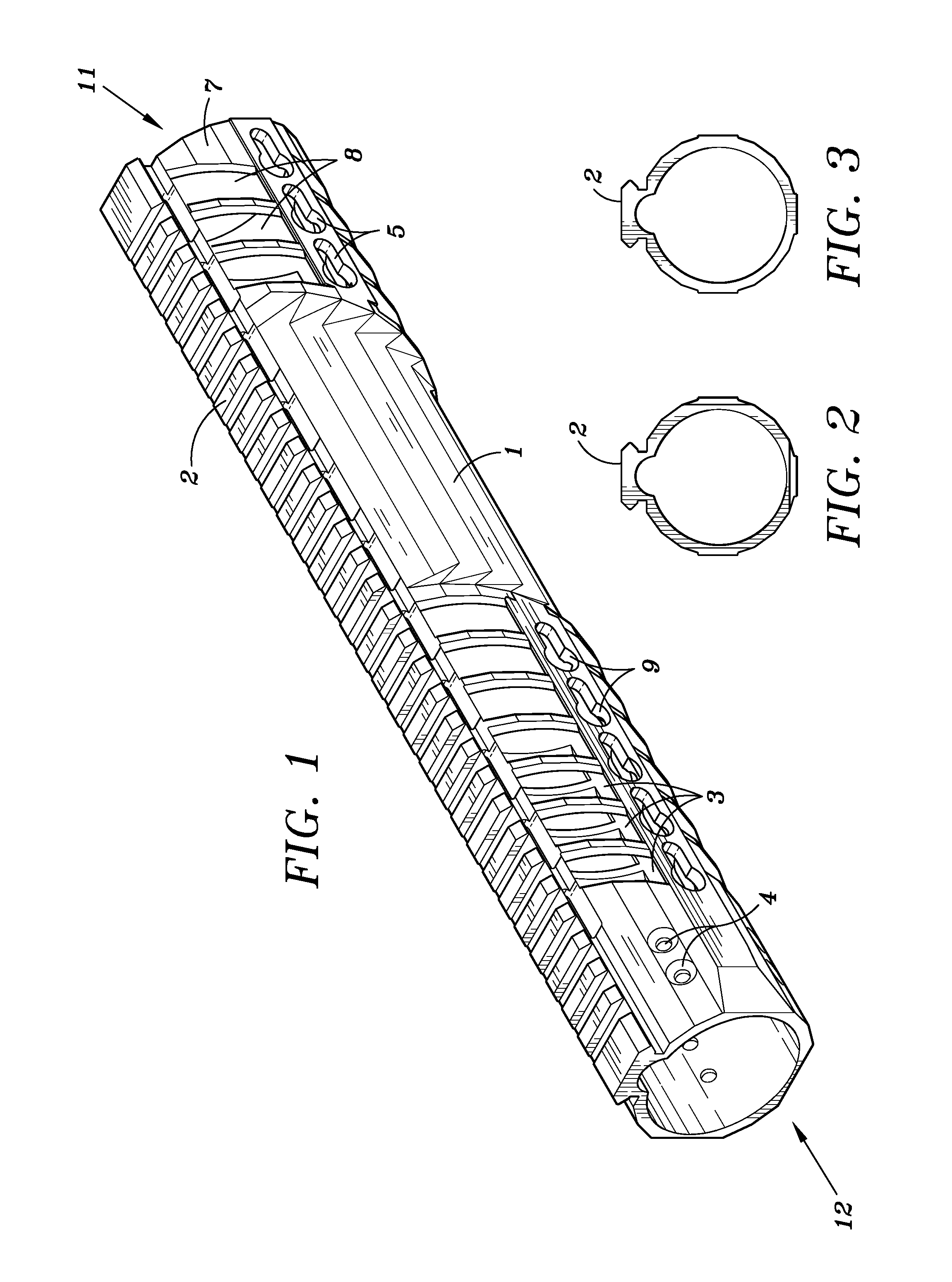
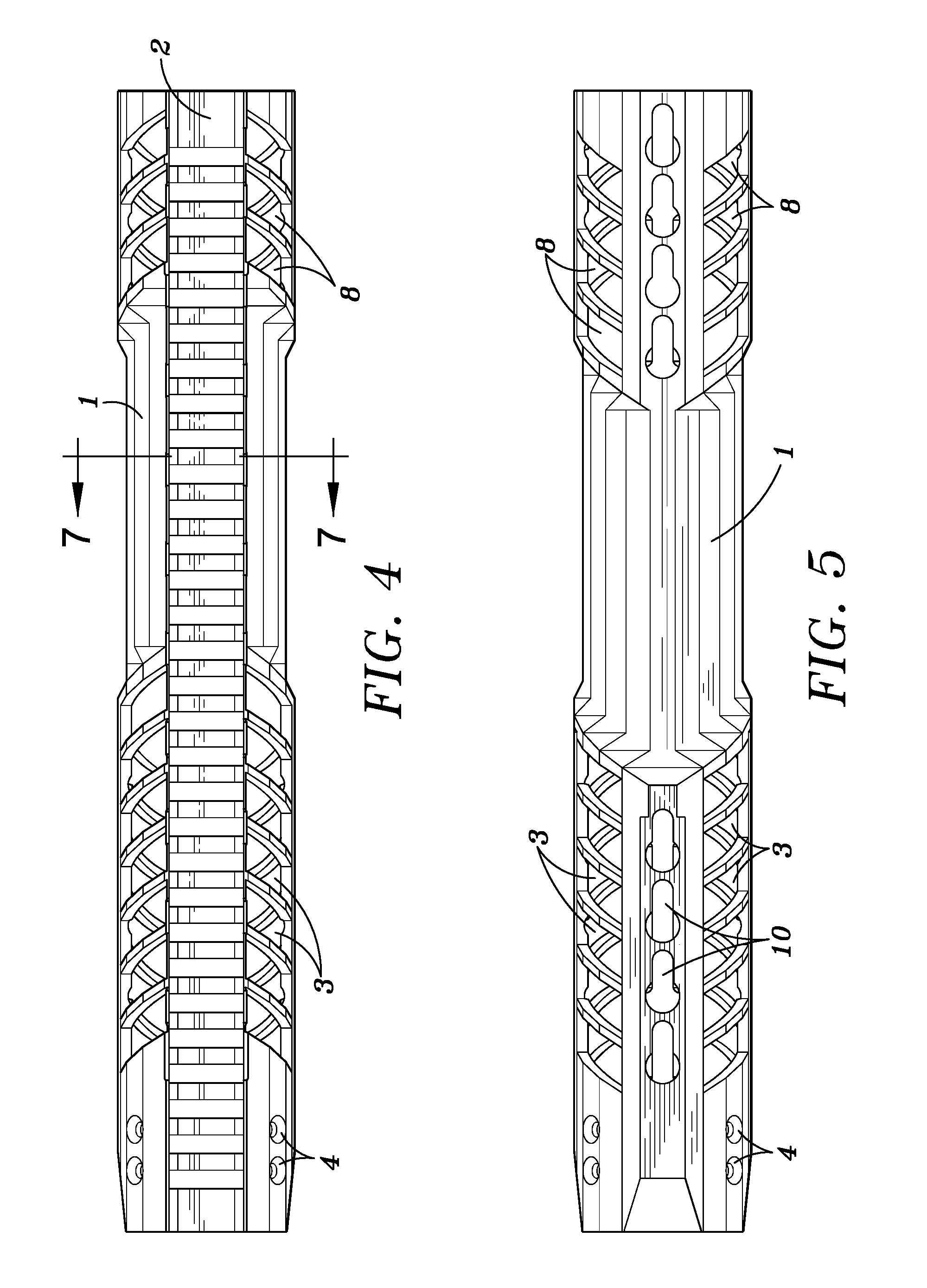
[0025]The present invention will be more fully understood and appreciated by reading the following Detailed Description in conjunction with the accompanying drawings, wherein like reference numerals refer to like components. FIG. 1 through FIG. 8 illustrate the gripping section and handguard of the present invention.

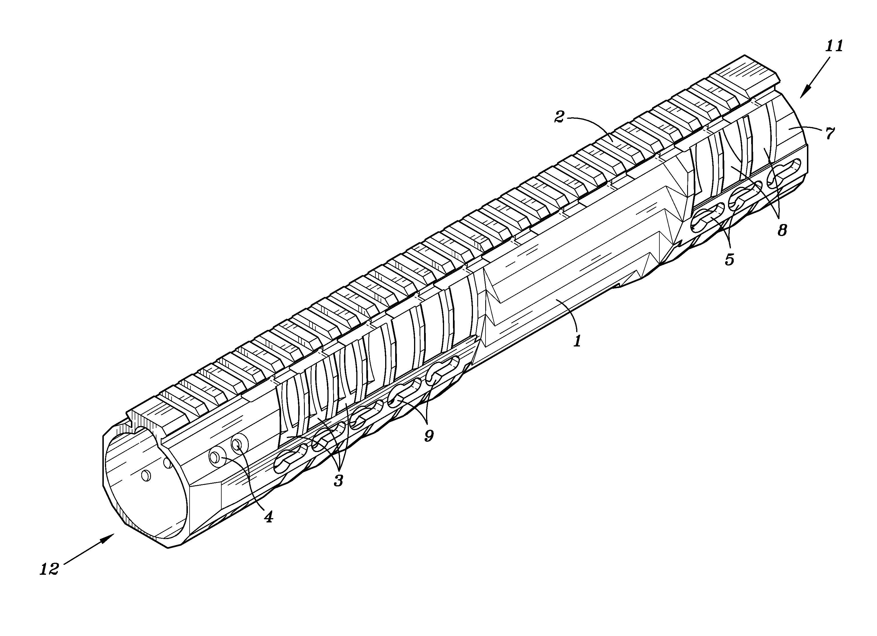
[0026]Referring to FIG. 1, an embodiment of the invention includes cylindrical member (7), gripping section (1), top mounting rail (2), forward ventilation cut-outs (8), rear ventilation cut-outs (3), screw holes (4), forward side bracket slots (5), rear side bracket slots (9), forward bottom bracket slots (6), and rear bottom bracket slots (10).

[0027]Cylindrical member (7) is a “free floating” handguard designed for a semiautomatic rifle. The “free floating” design is formed where the inner surface of cylindrical member (7) maintains radial spacing from the outer surface of the firearm barrel. As shown in FIG. 1, cylindrical member (7) has a cylindrical, tubular shape. ...


PUM


Abstract

This invention relates to a forearm “free floating” handguard for high rate of fire semiautomatic rifles and carbines such as the M16 family. More particularly, a handguard is disclosed that includes an integral gripping section and ventilation cut-outs, providing optimal grip strength, improved convective barrel cooling, while minimizing weight of the firearm.

Description

BACKGROUND OF INVENTION[0001]1. Field of the Invention[0002]This invention relates to the general field of forearm handguard assemblies for a rifles, and to the particular field of forearm handguards for high rate of fire semiautomatic rifles and carbines such as the M16 family of firearms.[0003]2. Description of Related Art[0004]Modern semiautomatic rifles enable rapid, high volume firing which can heat the barrel to very high temperatures. To protect the shooter from burns from the hot barrel, the barrel is usually surrounded by a handguard located directly in front of the receiver. In many cases, the handguard is vented to provide convective cooling and dissipate heat from barrel. An example of an early handguard can be seen in U.S. Pat. No. 2,965,994, “Gun forearm”.[0005]In addition to their heat protection function, handguards are commonly designed to attach weapon accessories such as optics, laser, night vision, foregrips, bipods, and tactical lights to the firearm. A current ...

Claims


Application Information

Patent Timeline
Patent Type & Authority Applications(United States)
IPC IPC(8): F41C23/16
CPCF41C23/16F41G11/003
Inventor WILLITS, CRAIG LARUE
Owner F 1 RESERACH LLC
Learn More