Dynamic power supply for light emitting diode

a technology of light-emitting diodes and power supply systems, applied in the direction of lighting devices, electrical equipment, light sources, etc., can solve the problems of degrading the performance of sourced leds, and reducing the efficiency of each converter. , to achieve the effect of maximizing the efficiency of the light-emitting diodes

Active Publication Date: 2017-01-19
KORRUS INC
View PDF10 Cites 6 Cited by
  • Summary
  • Abstract
  • Description
  • Claims
  • Application Information

AI Technical Summary

Benefits of technology

[0017]The disclosed invention permits both the efficiency of the light emitting diode (LED) to be maximized, while monitoring capacitor life. In addition, the invention allows reasonable action to be taken at the inevitable end of capacitor life to ensure acceptable lamp performance following the capacitor's failure. In one embodiment, the invention comprises both a monitoring and control system to dynamically regulate the voltage of the capacitor. The regulation configuration operates the capacitor at minimum possible voltage to maximize the efficiency, to compensate for component variations and dimming signal variations, while maintaining flicker-free LED output.

Problems solved by technology

This leads to what is referred to as systematic flicker, which although may not be directly observable, nonetheless leads to perceptible degradation in the quality of the light generated by the LED.
In addition, noise and other disturbances in the electric power signal also degrade the performance of sourced LEDs.
However, as this voltage is increased, each converter becomes less efficient.
In very small lamps such as the MR16, this leads to a very challenging tradeoff between efficiency, cost, and lamp size.
Eventually capacitor 112 ages and its capacitance is insufficient to prevent output ripple or possibly severe flicker.
Also, there is typically a design margin required on the set-point of the capacitor voltage (perhaps 25% higher than the LED voltage), which can significantly reduce the efficiency.
First, although the cascaded efficiency reduction of two power converters may be tolerable in applications in which the power supply is not inside a LED or lamp, inside an LED or lamp, the thermal conditions usually limit or define the performance envelope of the lamp.
In a typical two-stage power supply, when the capacitor's value drops below a certain design level (due to this aging process) it will no longer meet its specifications or may malfunction in an unpredictable way.

Method used


Image

  • Dynamic power supply for light emitting diode
  • Dynamic power supply for light emitting diode
  • Dynamic power supply for light emitting diode

Examples


Embodiment Construction

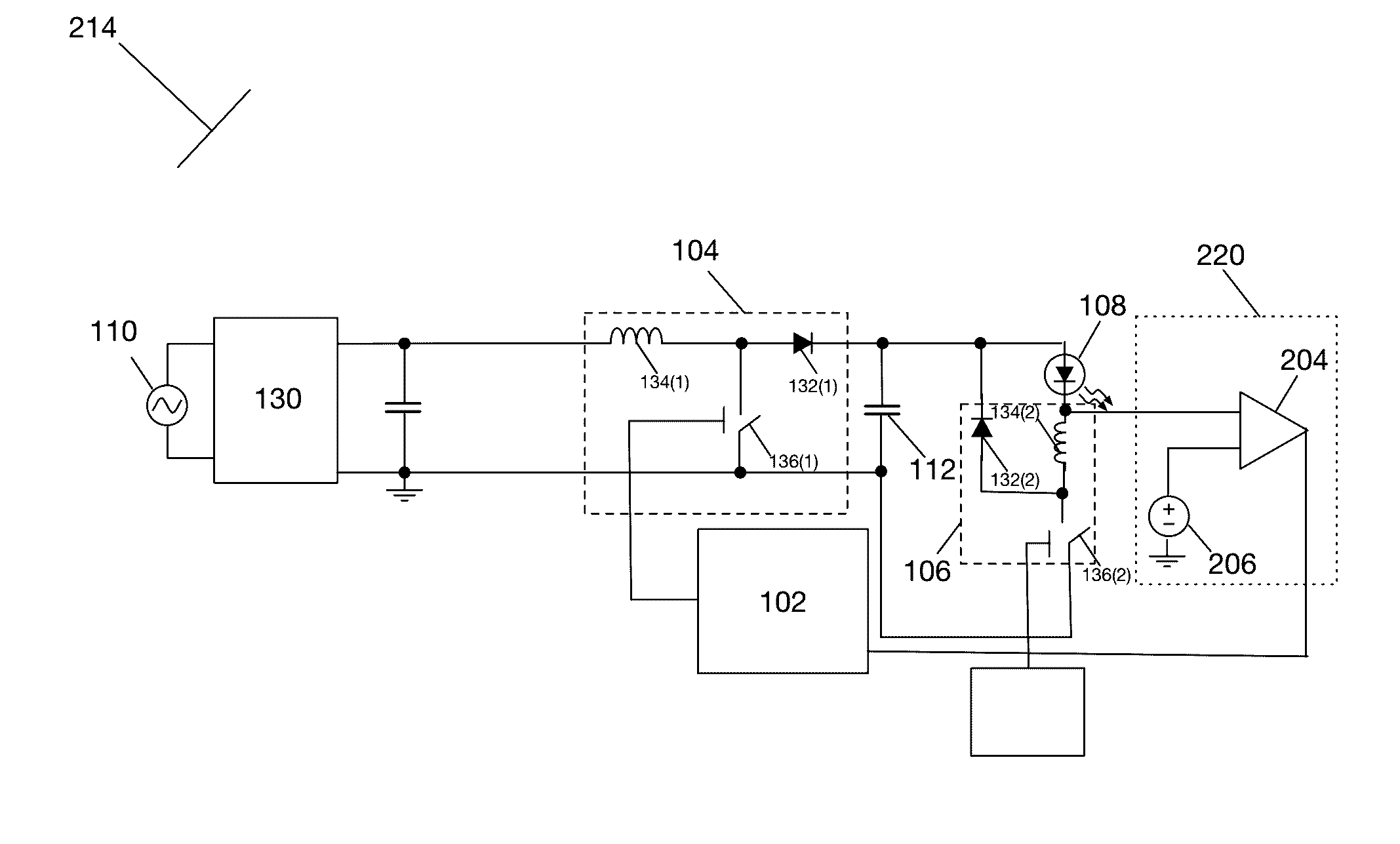
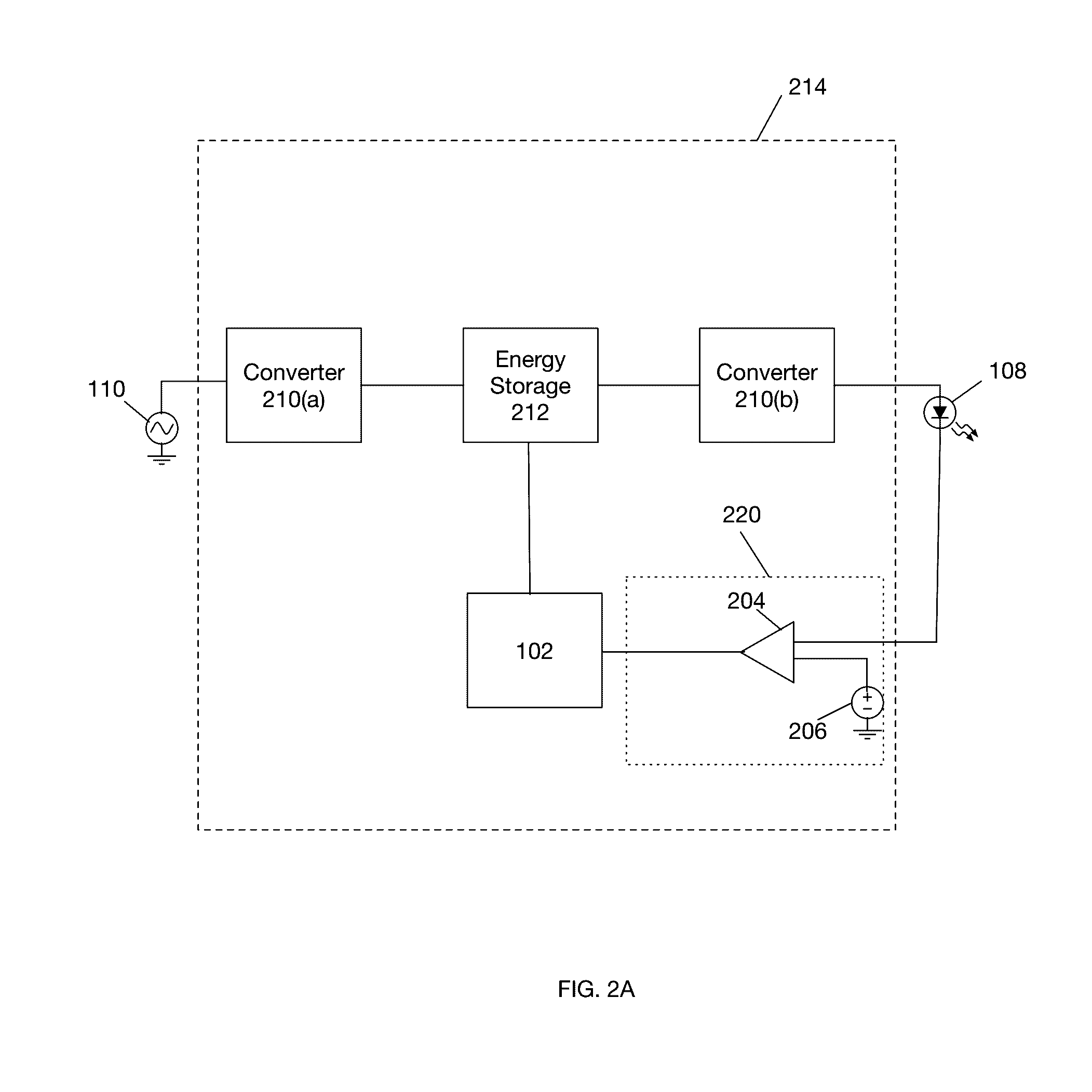
[0025]FIG. 2A is a block diagram of a dynamic power supply for powering an LED incorporating dynamic adjustment of an energy storage device according to one embodiment. As shown in FIG. 2A, dynamic power supply 214 comprises energy storage device 212, first voltage converter 210(a), second voltage converter 210(b), voltage control system 102 and detector 220. Energy storage device 212 may be a capacitor or other device for storing energy in electromagnetic or other form. First voltage converter 210(a) is electrically coupled to input voltage source 110 and energy storage device 212. Second voltage converter 210(b) is electrically coupled to energy storage device 212 and LED 108.

[0026]Converter 210(a) performs AC to DC conversion as well as voltage conversion of a received AC electromagnetic signal from power supply 110. In particular, converter 210(a) receives as input an alternating current (“AC”) electromagnetic signal from power supply 110 at a first voltage and generates as outp...


PUM


Abstract

A voltage control system for an LED operates to dynamically determine and set a minimum permissible voltage on an energy storage device such as a capacitor such that the energy storage device operates at a minimum possible voltage to compensate for component variations and dimming signal variations while maintaining flicker-free operation of the LED.

Description

CROSS-REFERENCE TO RELATED APPLICATIONS[0001]This application claims the benefit of U.S. Provisional Application No. 62 / 191,831, filed Jul. 13, 2015, the entire disclosure of which is incorporated herein by reference.FIELD OF INVENTION[0002]The subject matter herein relates generally to an electrolytic capacitor management system for lighting applications.BACKGROUND[0003]A conventional power supply for an LED lamp takes power from an input line at one voltage (typically 12V AC 50 / 60 Hz) and converts it to a higher DC voltage (e.g., 30 V DC) to power the LEDs. The temporal characteristics of the power signal directly impact the quality of the light generated by the LED. Thus, the power supply also regulates the current to the LEDs to provide consistent lighting output.[0004]Due to the zero crossings of the AC signal, which occur at twice the AC frequency, the power supplied to the LED is momentarily at zero. This leads to what is referred to as systematic flicker, which although may ...

Claims


Application Information

Patent Timeline
Patent Type & Authority Applications(United States)
IPC IPC(8): H05B33/08H05B44/00
CPCH05B33/0815H05B45/38H05B45/375
Inventor TAKACS, LASZLO
Owner KORRUS INC
Why Eureka
Try Eureka