

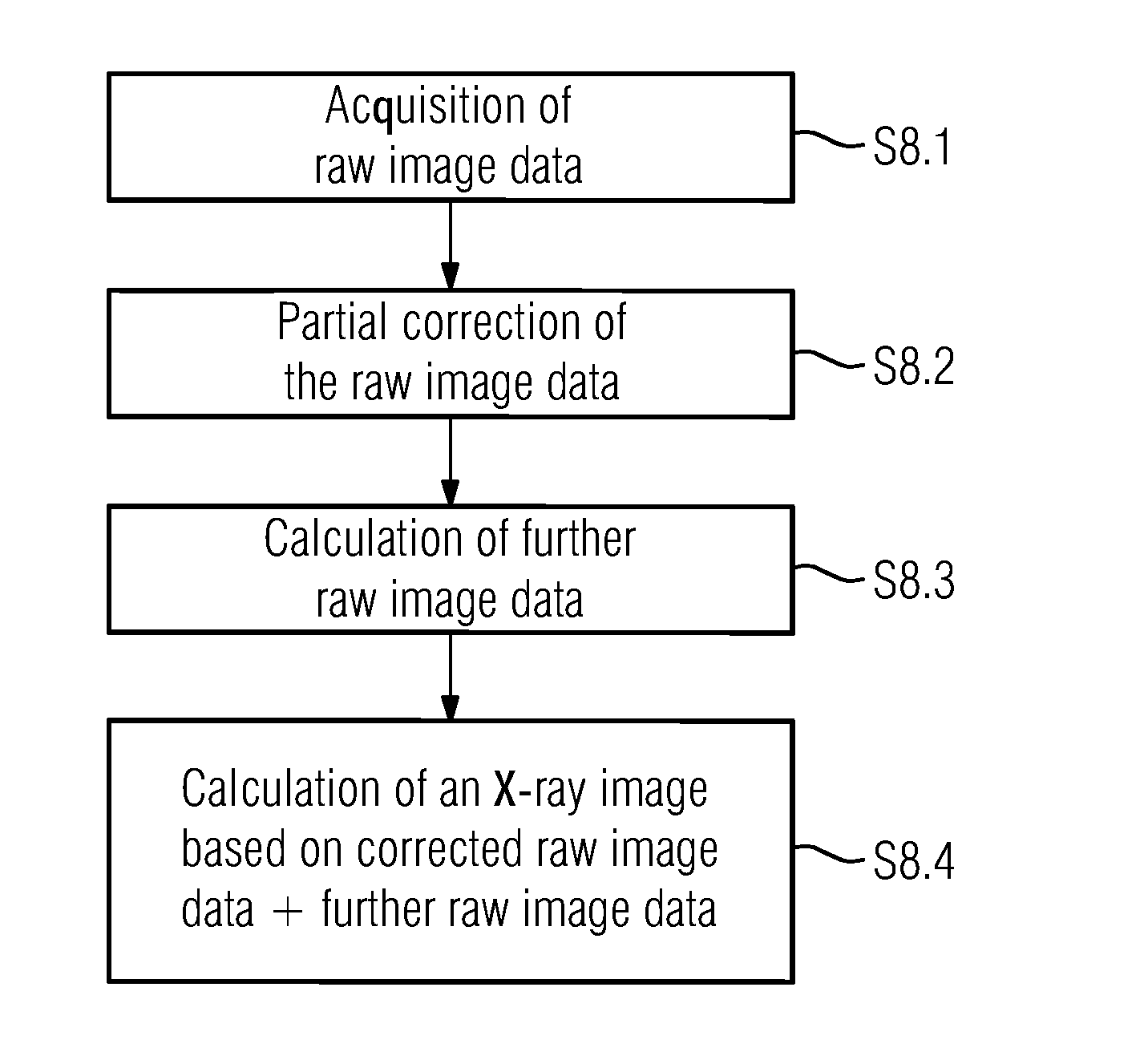
X-ray image generation
a technology of x-ray image and x-ray ray, which is applied in the field of generating x-ray images, can solve the problems of low pulse height, change in count rate behavior above the defined energy threshold, and general inability to realize, and achieve good or adequate spatial resolution and adequate signal quality.
- Summary
- Abstract
- Description
- Claims
- Application Information
AI Technical Summary
Benefits of technology
Problems solved by technology
Method used
Image

Examples
Embodiment Construction
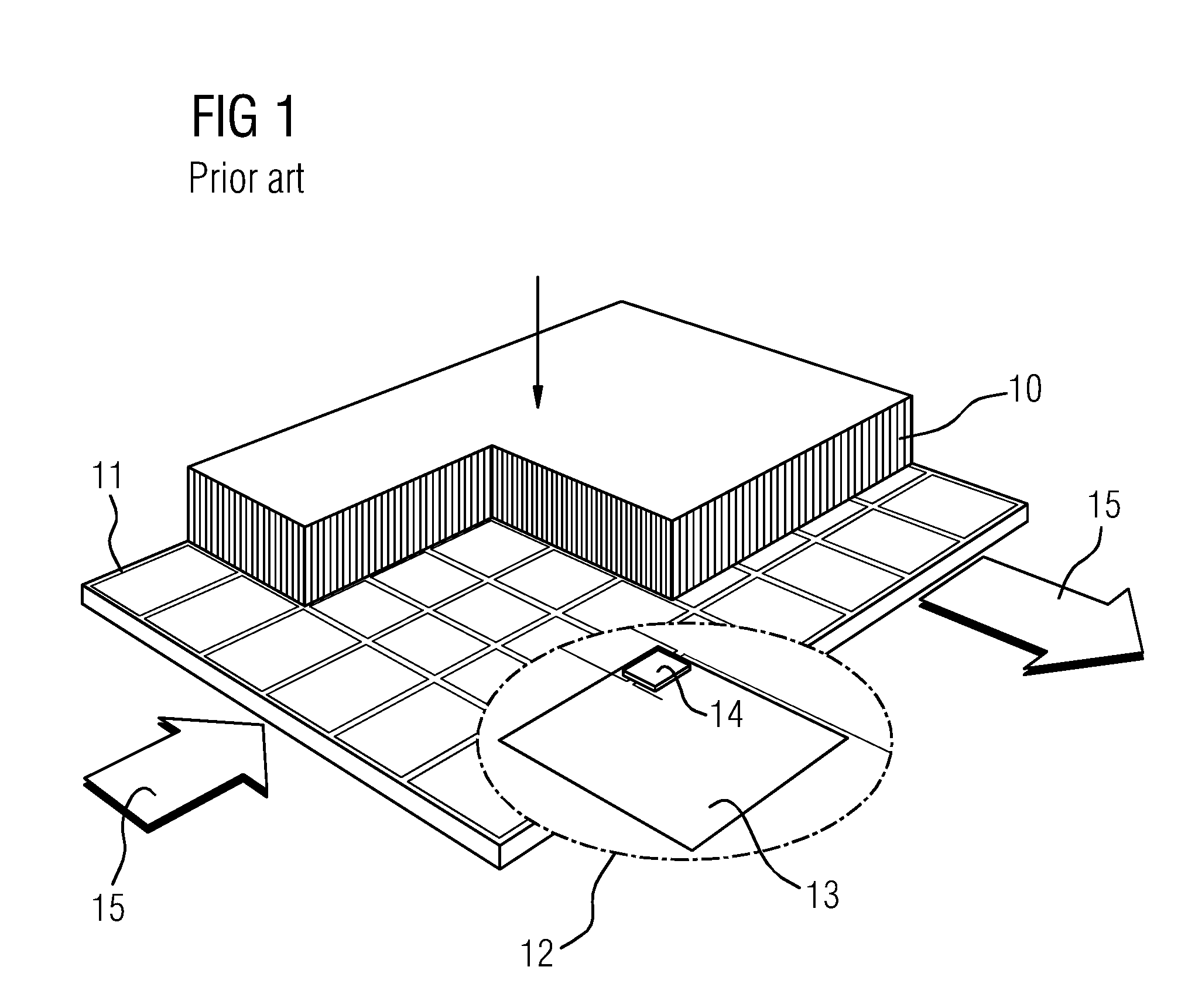
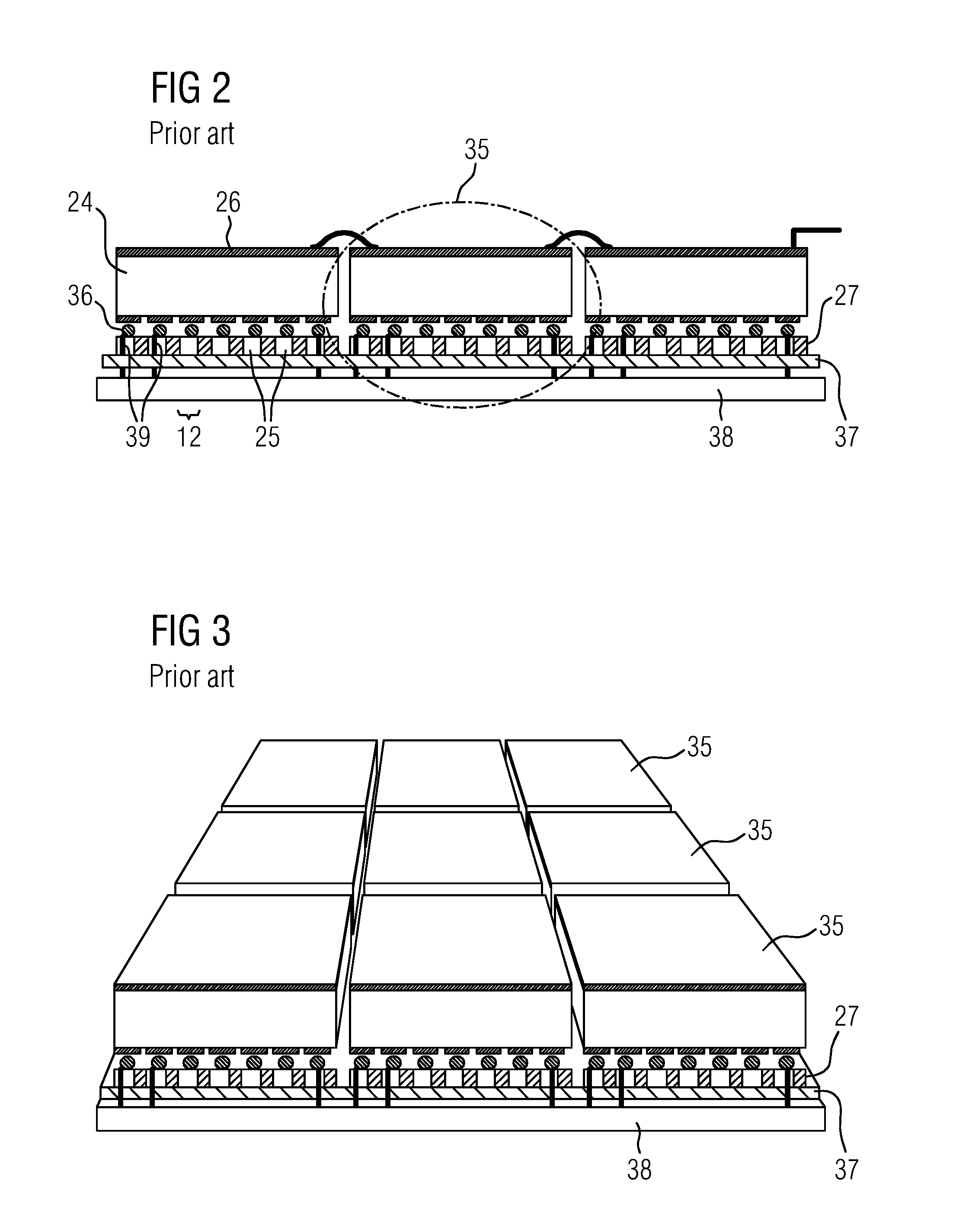
[0061]FIG. 7 shows a plan view onto four exemplary neighboring detector modules 24 of a counting digital X-ray detector 17, as may find application in combination with one or more of the present embodiments. The detector modules 24 shown are suitable for alignment next to one another on four sides, which provides that the X-ray detector 17 may have an arbitrary number of such detector modules 24 adjacent to one another. However, the detector modules 24 may also be rectangular or have some other shape that provides a regular matrix structure (e.g., hexagonal in the case of hexagonal pixels). In the present case, for greater clarity of illustration, each detector module 24 has only 5×5 pixels 12. A far greater number of pixels per detector module 24 may be provided. Each detector module 24 is subdivided into a plurality of equal-sized, square-shaped pixels 12 that are arranged in a matrix-like structure and have a regular pixel pitch 53.a as well as a regular pixel diagonal pitch 53.b...
PUM
 Abstract
Description
Claims
Application Information