Eureka AIR delivers breakthrough ideas for toughest innovation challenges, trusted by R&D personnel around the world.

Groundwater remediation system and method

a groundwater and remediation system technology, applied in water/sewage treatment by degassing, liquid degasification, separation processes, etc., can solve the problems of high cost of components, high cost of methods, and serious harm to people, other animals and plants, so as to maintain the porosity of filling material, reduce compaction, and reduce the effect of permeability

Active Publication Date: 2017-01-26
COUNCIL III EDWARD AUGUSTUS
View PDF0 Cites 3 Cited by
  • Summary
  • Abstract
  • Description
  • Claims
  • Application Information

AI Technical Summary

Benefits of technology

This patent describes a system for extracting, treating, and eliminating vapors from contaminated groundwater. The system includes a borehole with a liner and fill material around it. The fill material can help to degrade contaminants in the vapors. The system also has an aeration tube which extends through the fill material and has a small air gap at the bottom of the borehole. The system can be used to extract vapors from groundwater and soil by manipulating variations in atmospheric pressure. A ground cover can be added to the top of the borehole to reduce compaction and maintain porosity. The technical effect is an effective and efficient means to extract, treat, and eliminate vapors from contaminated groundwater.

Problems solved by technology

Groundwater contamination related to volatile or semi-volatile compounds is common and can cause serious harm to people, other animals and plants.
Sources of groundwater contamination include leaking pipelines, chemical spills, landfills and transportation mishaps.
All of these prior known groundwater remediation systems and methods require expensive groundwater treatment wells and above ground infrastructure to support or control the groundwater remediation activities.
The prior known remediation systems include various blowers, pumps and other components that are often expensive.
Power to run the mechanical and electrical components, as well as the ongoing equipment maintenance activities adds to the cost.
In addition, regulatory requirements in many states require that treatment wells and other components be removed after the systems are no longer in use, adding to the costs associated with operating these prior known remediation systems.
The time needed to complete the groundwater remediation often takes years to decades of time with prior known remediation methods and systems.
The wells in prior known remediation systems are also limited in location as the above ground components are restricted to areas where near ground obstructions are not a hazard to transportation systems or pedestrians.

Method used


Image

  • Groundwater remediation system and method
  • Groundwater remediation system and method

Examples


Embodiment Construction

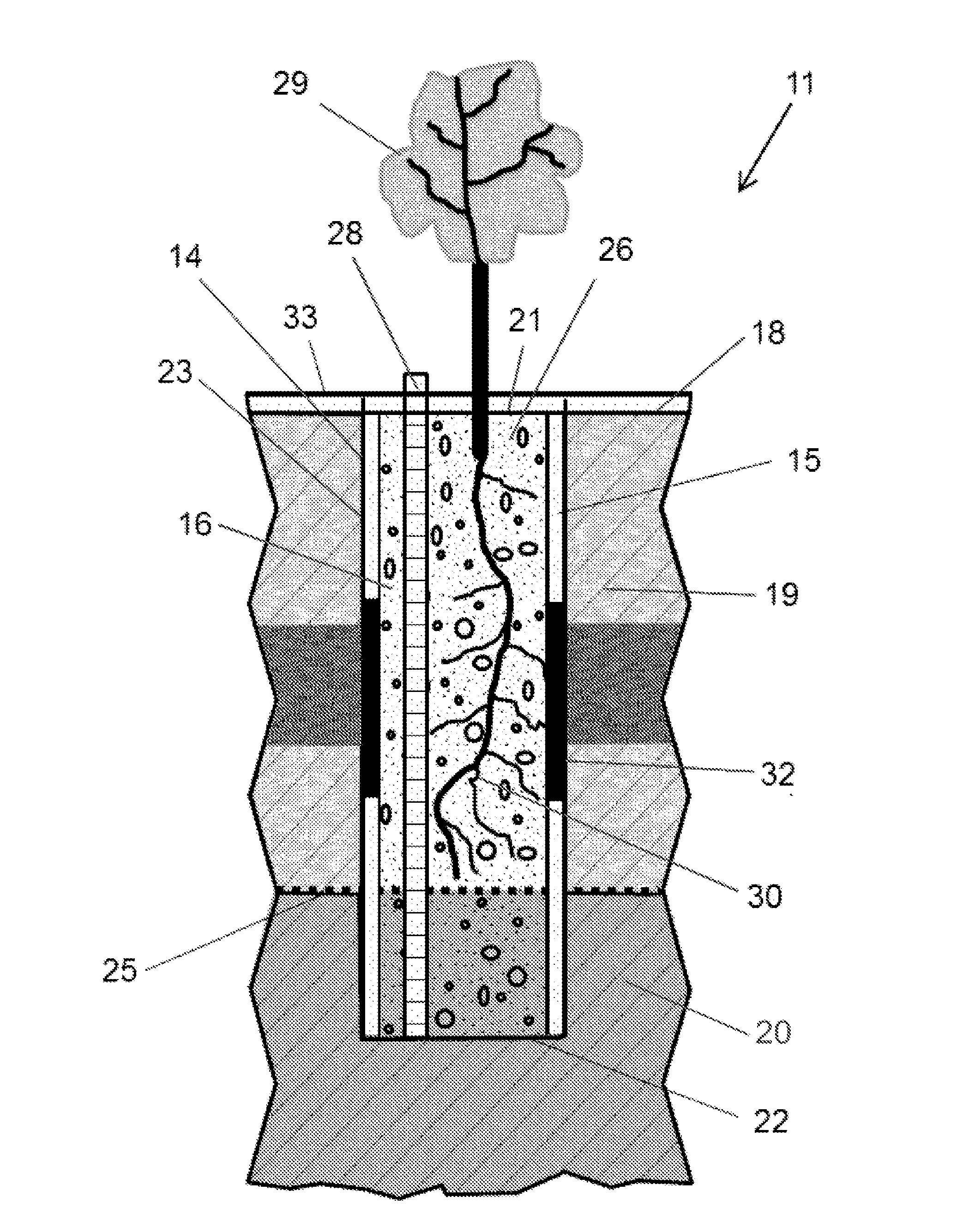
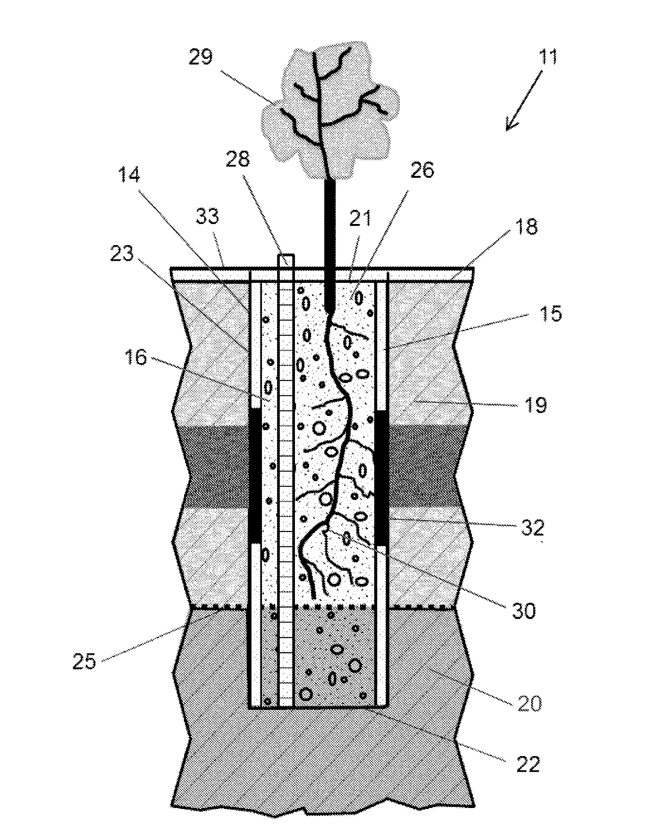
[0013]Referring to the FIGURE, a system 11 for intercepting, treating and venting vapors from contaminated groundwater, embodying features of the present invention, includes one or more spaced boreholes 14 each having a liner 15 and fill material 16. Each borehole 14 is drilled from ground level 18 downwardly to a selected depth through the soil 19 and into the groundwater 20. The borehole 14 has an open top end 21 at ground level 18, a spaced bottom end 22, and an inwardly facing outer wall 23 of the soil 19 that extends from the top end 21 to the bottom end 22. Preferably the bottom end 22 is located several feet below the water table 25. The borehole 14 defines a borehole cavity 26.

[0014]The liner 15 fits into the borehole 14 adjacent to the outer wall 23, and extends from the top end 21 to the bottom end 22. The liner 15 is gas permeable and can be made from organic or inorganic mesh. The liner 15 reduces and prevents fine grain particles in the soil 19 migrating into the boreho...


PUM

PropertyMeasurementUnit
atmospheric barometric pressureaaaaaaaaaa
diameteraaaaaaaaaa
porosityaaaaaaaaaa

Abstract

A system for intercepting, treating and venting vapors from contaminated groundwater includes a borehole that extends into the groundwater and has an open top end, a porous liner against the outer wall of the borehole and porous fill material inside the liner. The fill material can include materials to retard and degrade contaminants in the vapors. The system can include a slotted aeration tube in the borehole, vegetation planted in the open end of the borehole, impermeable sections in the liner, and impermeable ground cover around the top end of the borehole. A method for intercepting, treating and venting of vapors from contaminated groundwater includes the system and pulling vapors out the top end of the borehole with variations in atmospheric barometric pressure.

Description

TECHNICAL FIELD[0001]The present invention relates to groundwater remediation, and more particularly to a passive system and method for intercepting, treating and venting volatile and semi-volatile contaminants from groundwater.BACKGROUND ART[0002]Groundwater contamination related to volatile or semi-volatile compounds is common and can cause serious harm to people, other animals and plants. The United States spends billions of dollars each year treating groundwater contamination. Sources of groundwater contamination include leaking pipelines, chemical spills, landfills and transportation mishaps. Chemicals released at or near the ground surface can migrate through the vadose zone and into the groundwater.[0003]The vadose zone, between the ground surface and the water table, generally consists of subsurface sediments that were deposited in substantially horizontal layers. Porosity levels vary from layer to layer with the conductance of fluids and soil gases usually much greater in t...

Claims


Application Information

Patent Timeline
Patent Type & Authority Applications(United States)
IPC IPC(8): B09C1/00C02F3/34B01D19/00C02F1/20
CPCB09C1/002C02F1/20C02F2201/002B01D19/0073C02F2103/06C02F3/34B09C1/005B09C1/10
Inventor COUNCIL, III, EDWARD AUGUSTUS
Owner COUNCIL III EDWARD AUGUSTUS
Why Eureka
Eureka Blog
Learn More