Multi Mode Wave Energy Converter With Elongated Wave Front Parallel Float Having Integral Lower Shoaling Extension

a wave front and wave energy converter technology, applied in the field of wave energy converters, can solve the problem of high capital cost (capex)

Active Publication Date: 2017-01-26
ROHRER TECH
View PDF12 Cites 8 Cited by
  • Summary
  • Abstract
  • Description
  • Claims
  • Application Information

AI Technical Summary

Benefits of technology

[0029]Most embodiments of the present disclosure describe EWFP floats and floating frames which are self-aligning parallel to predominant oncoming wave fronts using a weather vanning effect by having mooring lines attached to the frame pivotably connected to an up sea submerg...

Problems solved by technology

Unfortunately, Salter's scaled wave tank experiments found that good wave energy capture efficiency required very large Duck float central cylinder diameters (see prior reference to 1977 Nature article above).
They require a wide (to intercept more wave front) large diameter (6-18 meter) wat...

Method used


Image

  • Multi Mode Wave Energy Converter With Elongated Wave Front Parallel Float Having Integral Lower Shoaling Extension
  • Multi Mode Wave Energy Converter With Elongated Wave Front Parallel Float Having Integral Lower Shoaling Extension
  • Multi Mode Wave Energy Converter With Elongated Wave Front Parallel Float Having Integral Lower Shoaling Extension

Examples


Embodiment Construction

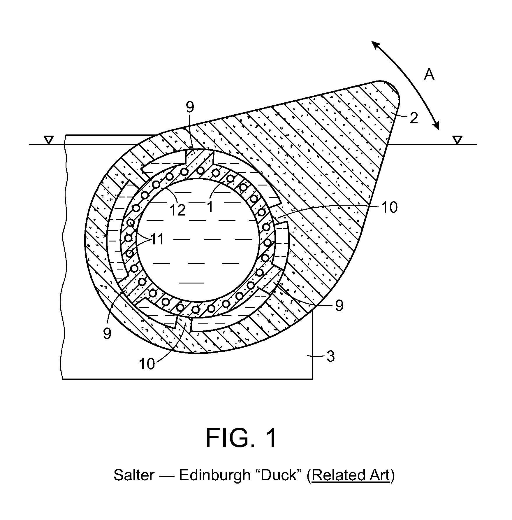
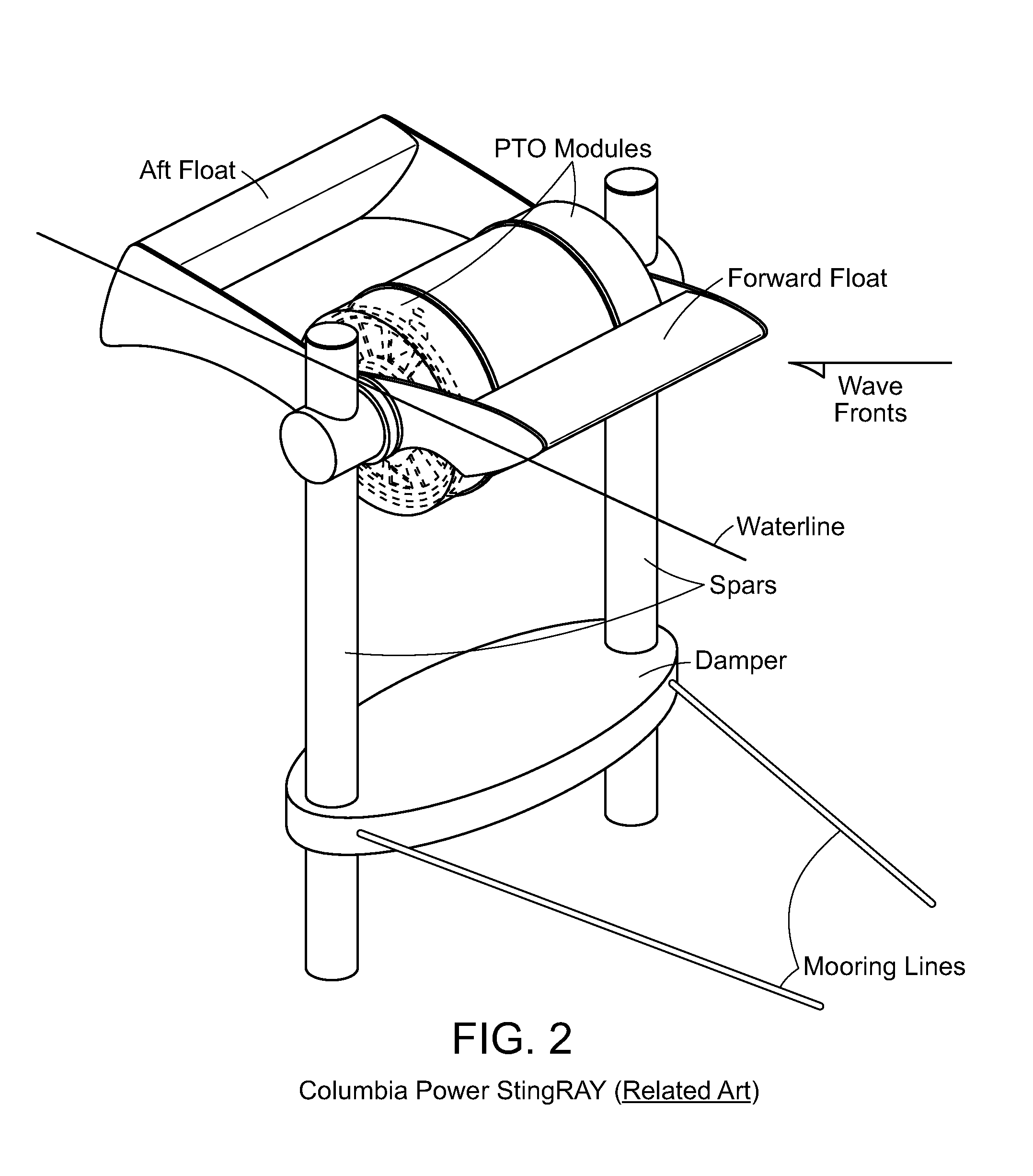
[0041]FIG. 1 and FIG. 2 of the Salter Duck and the Columbia StingRay, respectively, are related prior art and are described in their references cited including GB1482085 (Salter) and US 2015 / 0252777 (Rhinefrank). They are also described and distinguished from the present disclosure in the BACKGROUND OF THE DISCLOSURE and SUMMARY OF THE DISCLOSURE sections above.

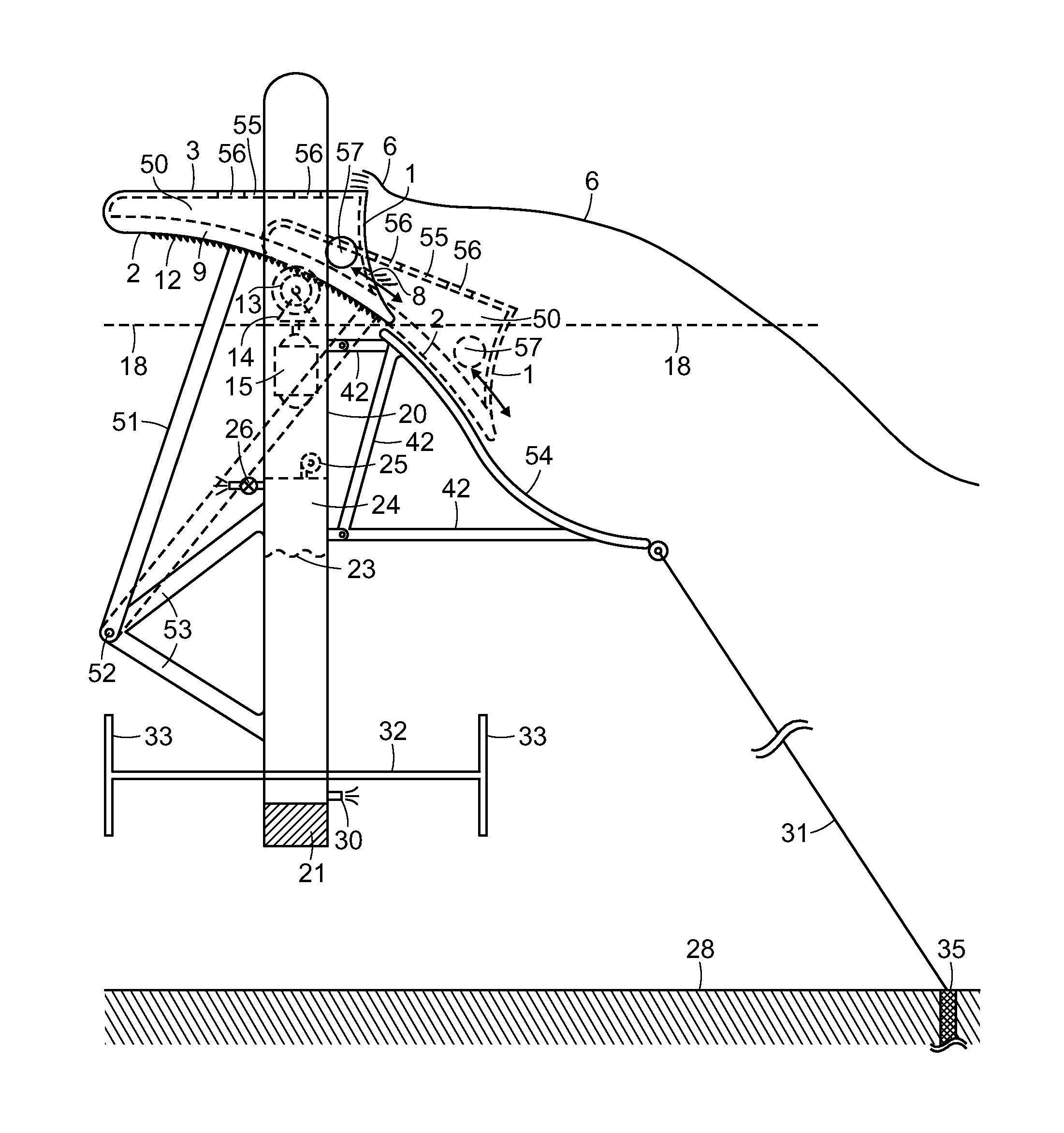
[0042]FIG. 3 and FIG. 4 are described in Rohrer U.S. Pat. No. 9,127,640 and Rohrer US 2015 / 0082785, respectively, both of which are incorporated herein by reference and both of which this application is a continuation-in-part. The element numbers used in FIG. 4 and FIG. 5 are consistent with those used to describe the present disclosure.

[0043]FIG. 3 describes a float 3 rotatably attached by swing arms 51 to a buoyant vertical spar frame 20 at pivot point or pivot axis 52. The generator 15 is housed within frame column 20 and driven by rack gear 12 on the float bottom through pinion gear 13 on the frame 20. The FIG. 3 embodime...


PUM


Abstract

A wave barrier or wave terminator type ocean wave energy converter (WEC) utilizing one or multiple adjacent floats together forming an elongated wave front parallel (EWFP) float rotatably connected by at least one swing or drive arm to a secondary floating or shore or seabed fixed body or frame, such that the at least one swing arm is rotating about a submerged pivot point or axle on such body or frame and constraining the motion of the float(s) relative to the body or frame when wave forces are applied against the float(s). Relative to the direction of oncoming wave fronts and relative to the still water line (SWL), the at least one EWFP float is substantially forward of, and above, the pivot point such that the float concurrently moves both upward and rearward on wave crests and returns both forward and downward on ensuing wave troughs. The rear surface of the EWFP float is substantially arcuate and concave with a radius approximating its distance from the pivot point such that the float produces minimal energy consuming back waves when it is being moved by oncoming wave forces. The lower rear arcuate surface of the float can extend below the bottom of the float deeper into the water column to capture additional wave energy.

Description

CROSS-REFERENCE TO RELATED APPLICATIONS[0001]This is a Continuation-In Part of U.S. Regular Utility application Ser. No. 14 / 530,723, filed Nov. 1, 2014, which is a Continuation-in-Part of U.S. Regular Utility application Ser. No. 14 / 101,325, filed Dec. 9, 2013, now U.S. Pat. No. 9,127,640, issued Sep. 8, 2015, which is a Continuation-In-Part of U.S. Regular Utility application Ser. No. 13 / 506,680, filed May 8, 2012, now U.S. Pat. No. 8,614,520, issued Dec. 24, 2013, and claims the benefit of U.S. Provisional Application Ser. No. 62 / 284,640 filed Oct. 5, 2015, the contents all of which are incorporated in their entirety herein by reference.FIELD OF THE DISCLOSURE[0002]This disclosure relates to the production of electrical power, pressurized water, or other useful work from surface waves on a water body. More particularly, this disclosure relates to Wave Energy Converters (“WEC”) of the wave terminator or barrier type, wherein one or more elongated buoyant surface floats or bodies, o...

Claims


Application Information

Patent Timeline
IPC IPC(8): F03B13/18H02K7/18
CPCH02K7/18F03B13/1815F03B13/182F03B13/186F05B2270/18Y02E10/30
Inventor ROHRER, JOHN W.
Owner ROHRER TECH
Why Eureka
Try Eureka