Supercharge Your Innovation With Domain-Expert AI Agents!

Thermal storage ice breaker apparatus

a technology of thermal storage and ice breaker, which is applied in the direction of domestic cooling apparatus, lighting and heating apparatus, heating types, etc., can solve the problems of inconvenient water meniscus around the projection, and achieve the effect of low discharge temperature and constant, and very good thermal conductivity of the projection

Active Publication Date: 2017-01-26
EVAPCO
View PDF7 Cites 0 Cited by
  • Summary
  • Abstract
  • Description
  • Claims
  • Application Information

AI Technical Summary

Benefits of technology

The present invention solves the problem of temperature rise during melt by using a tube structure that allows ice to break free from the tube near the initiation of melting. This results in a lower discharge temperature and constant temperature. The invention also prevents the formation of an inconvenient meniscus of water around the probe by utilizing special projections on the tube that enable ice to break out much sooner. This results in better conduction of heat from the tube to the bulk ice-water in the tank.

Problems solved by technology

The inventors discovered during testing of stainless steel ice thickness probes, if the probe passed to the outside of the ice to the tank water, an inconvenient meniscus of water formed around the projection.

Method used


Image

  • Thermal storage ice breaker apparatus
  • Thermal storage ice breaker apparatus
  • Thermal storage ice breaker apparatus

Examples


Embodiment Construction

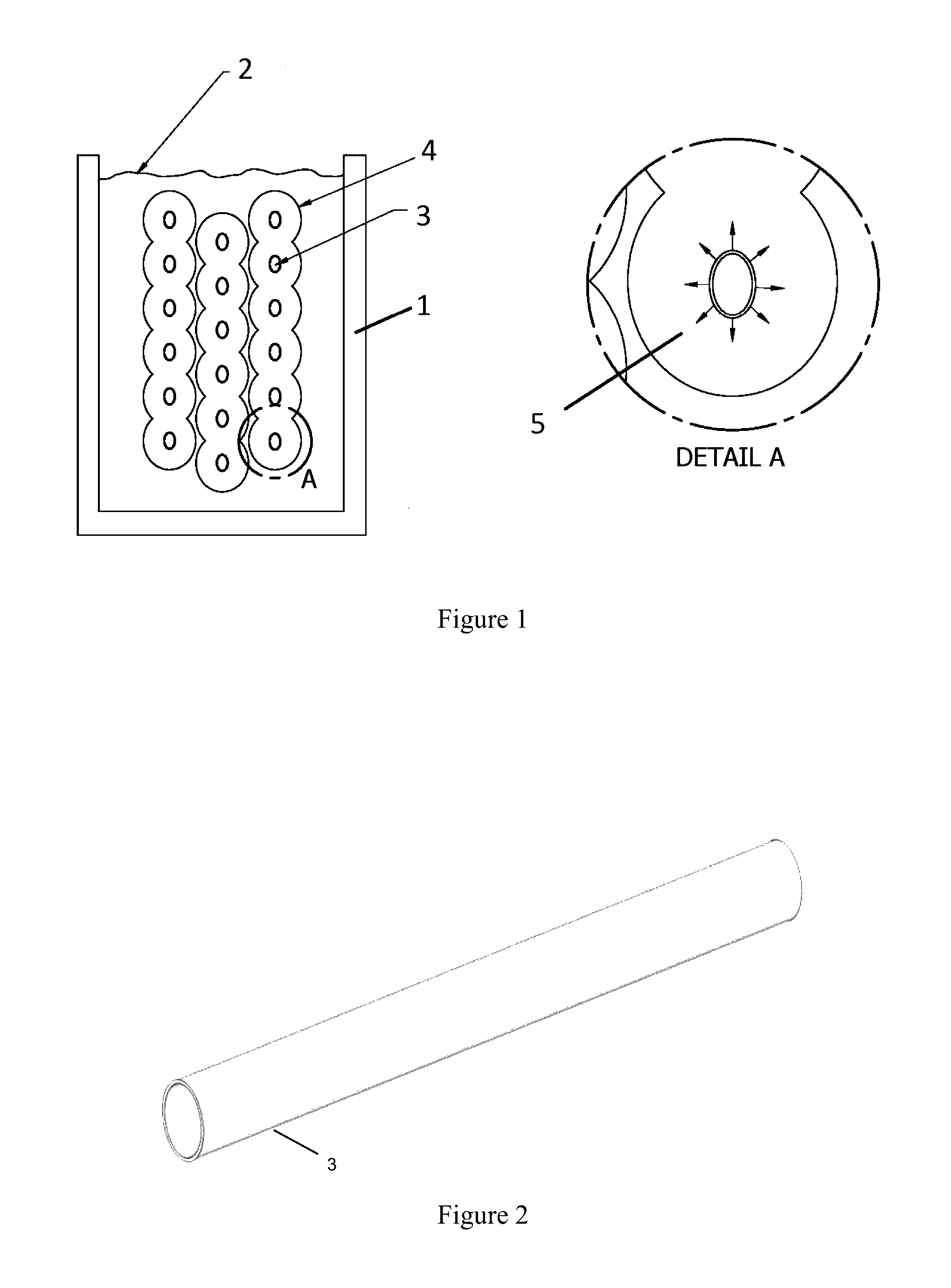
[0026]FIG. 1 shows the major components of a prior art internal melt ice coil system in cross section. Ice water tank 1 holds a plurality of tubes 3 filled with glycol. The plurality of tubes 3 is submerged in water 2. When cold glycol flows through the plurality of tubes 3, the water 2 is converted to ice 4 around the tubes 3. Detail A shows a close-up view of the tube 3 and ice 4 with its melt direction 5 away from the tube surface.

[0027]FIG. 2 illustrates an isometric view of a prior art ice coil tube.

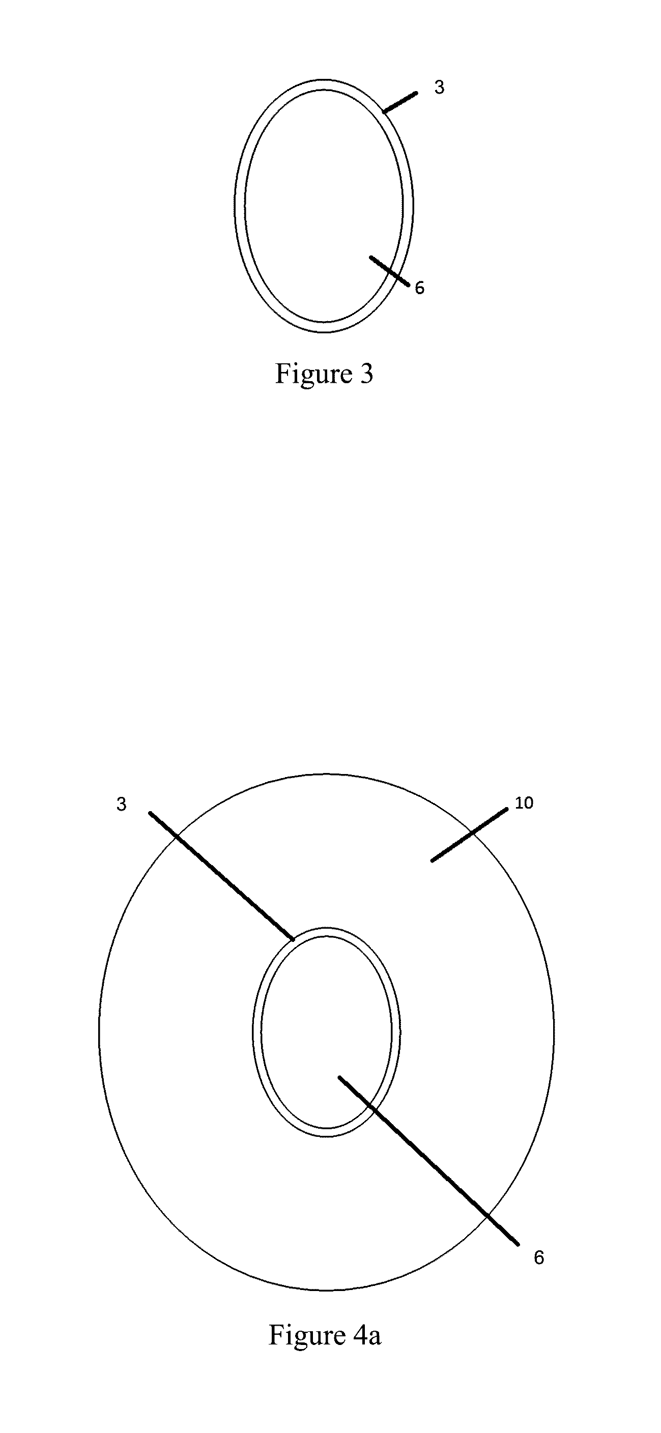
[0028]FIG. 3 shows a cross section of the tube in FIG. 2. In use, the tube 3 surrounds a glycol solution 6.

[0029]FIG. 4a shows an ice coil tube with ice build in cross section. An ice coil tube 3 is filled with a cold glycol solution 6 that has previously built a layer of ice 10 around the tube 3.

[0030]FIG. 4b shows an ice coil tube with ice first starting to melt. Tube 3 contains a warm glycol solution which has initiated heating of the tube. A meniscus of water 12 forms as the ice...


PUM


Abstract

An internal melt ice thermal storage device having an ice build / melt coils with tubes fitted with extensions or “fins” that transfer heat from the thermal transfer medium in the tubes to distal portions of the ice rings that surround said tubes in order to define the shape of the liquid meniscus between the tube and ice allowing the ice to break free from the tube near the initiation of melt.

Description

FIELD OF THE INVENTION[0001]This invention relates to methods and apparatuses for thermal storage.BACKGROUND OF THE INVENTION[0002]Thermal ice storage systems have recently been migrating to internal melt systems because of the ease of maintenance and simplicity of construction inherent to these systems as compared to external melt systems. One of the major hurdles of internal melt systems is the rise in glycol temperature over time during the melt cycle before the ice “breaks out,” dislodging from the tube and exposing the coil surface to the bulk liquid water in the tank. It is well known that internal melt thermal ice storage systems are limited in their ability to provide consistent glycol supply temperature during melt. This is due to the meniscus of liquid water that forms between the ice and tube during the melt and before breakout. This meniscus is very still, hence transfers heat at a low rate between the tube and ice, effectively insulating the coil surface from the ice. T...

Claims


Application Information

Patent Timeline
Patent Type & Authority Applications(United States)
IPC IPC(8): F28D20/00F25D3/00
CPCF25D3/005F28D20/0034C09K5/06F24F5/0017F25C5/10F28D20/02F28F1/10Y02E60/14
Inventor VADDER, DAVEYKANE, JEFF
Owner EVAPCO
Features
  • R&D
  • Intellectual Property
  • Life Sciences
  • Materials
  • Tech Scout
  • Unparalleled Data Quality
  • Higher Quality Content
  • 60% Fewer Hallucinations
Learn More