Compensation Design of Power Converters

Active Publication Date: 2017-01-26
TEXAS INSTR INC
View PDF5 Cites 4 Cited by
  • Summary
  • Abstract
  • Description
  • Claims
  • Application Information

AI Technical Summary

Benefits of technology

The present invention offers methods and systems for designing compensation networks in power converters. These methods involve computing optimal values for compensation components based on loop specifications, such as crossover frequency, phase margin, gain margin, and low frequency gain, and applying changes to the power converter design accordingly. The invention provides a power converter design system comprising a component database, a design tool, and a compensation design tool, which facilitates the selection of suitable bill of materials passive components for the compensation network based on computed compensation values. The technical effects include improved design efficiency and performance of power converters.

Problems solved by technology

Compensation design for switching power converters can be a difficult and time consuming process requiring many manual iterations to find a design that meets all the desired loop specifications.

Method used


Image

  • Compensation Design of Power Converters
  • Compensation Design of Power Converters
  • Compensation Design of Power Converters

Examples


Embodiment Construction

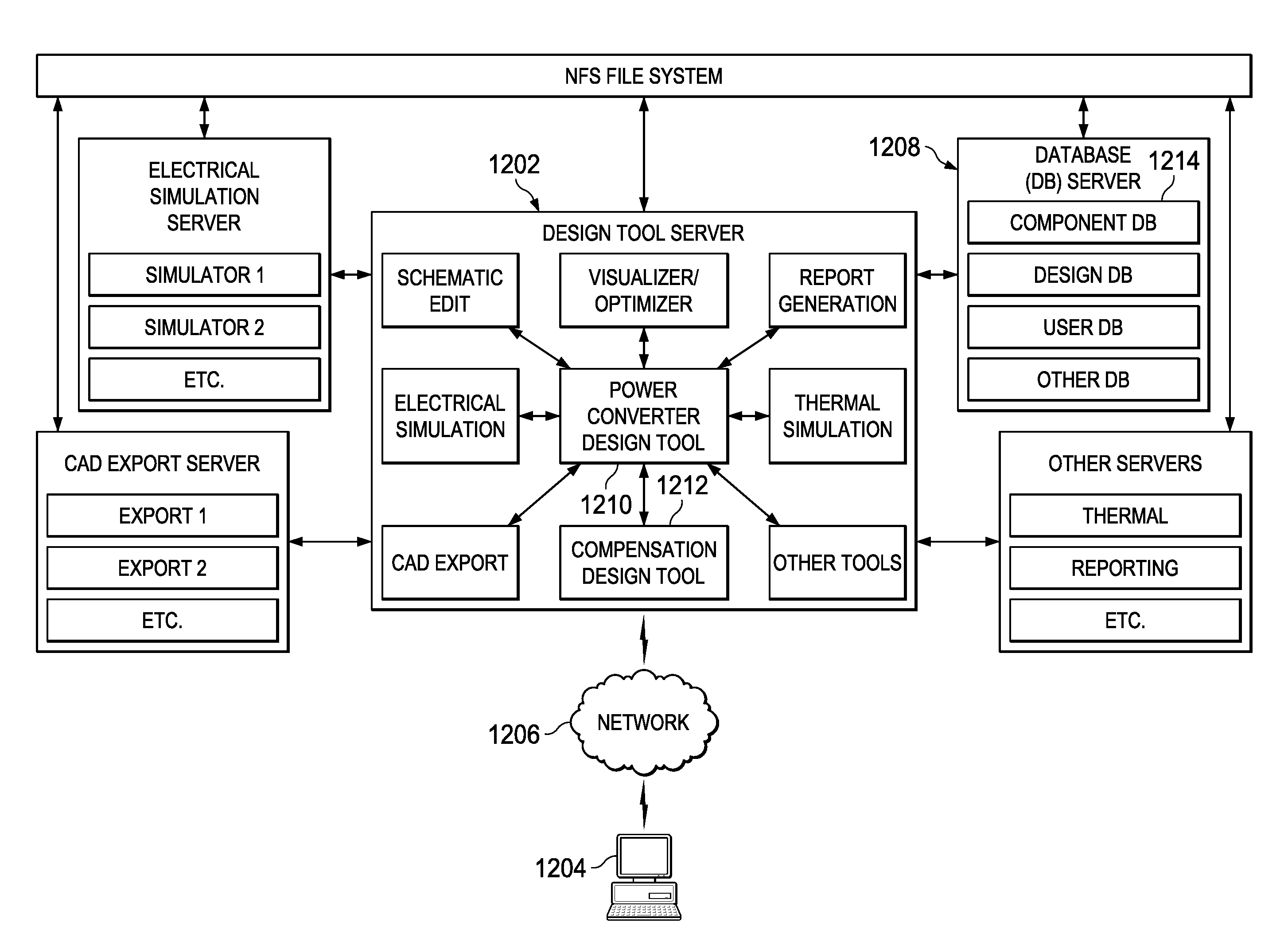
[0021]Specific embodiments of the disclosure will now be described in detail with reference to the accompanying figures. Like elements in the various figures are denoted by like reference numerals for consistency.

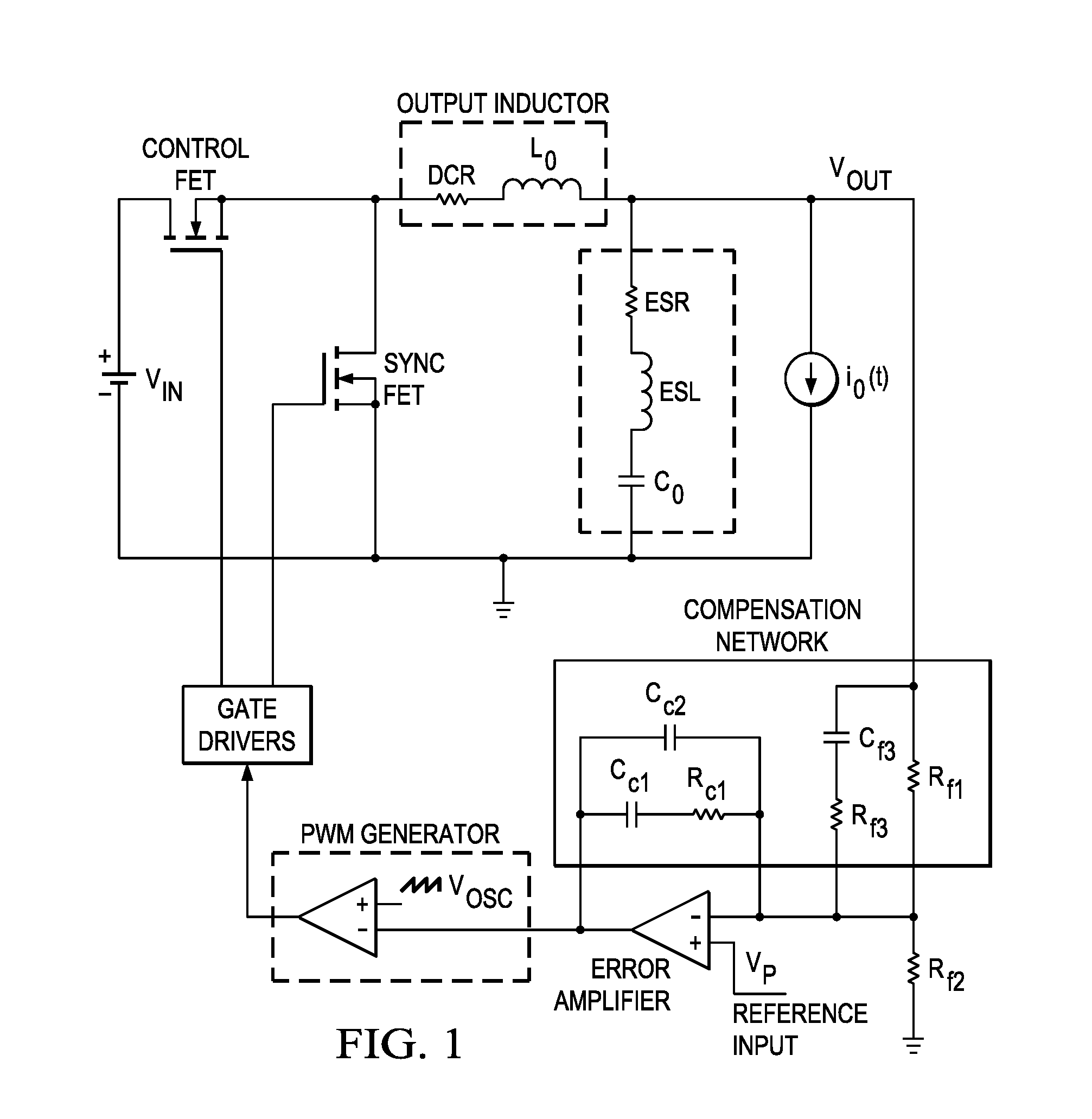
[0022]As previously mentioned, compensation design for switching power converters can be a difficult and time consuming process. A poorly designed compensation network can lead to unstable operation possibly resulting in undesired oscillations in output voltage, audible noise from the inductor and capacitors, over heating of the switches, inductor and output capacitor, reduced life of the power supply, and damage to the circuits powered by the converter. Performing compensation design manually is not only time consuming, but is also prone to inaccuracies as key design parameters such as operational amplifier (Op Amp) bandwidth and finite open loop gain or converter parasitics are typically ignored to simplify the design equations. Manually ensuring that a compensation desig...


PUM


Abstract

A method for compensation network design in a power converter design system is provided that includes computing optimal values for compensation components in a compensation network based on a plurality of loop specifications comprising crossover frequency (Fco), phase margin (PM), Gain Margin (GM), and low frequency gain (LFG), and applying changes to a power converter design comprising the compensation network based on the optimal values.

Description

CROSS-REFERENCE TO RELATED APPLICATIONS[0001]This application claims benefit of U.S. Provisional Patent Application No. 62 / 196,204 filed Jul. 23, 2015, which is incorporated herein by reference in its entirety.BACKGROUND OF THE DISCLOSURE[0002]Field of the Disclosure[0003]Embodiments of the present disclosure generally relate to design of power converters, and more specifically relate to compensation design of power converters.[0004]Description of the Related Art[0005]The design of a switching power converter is usually performed in two stages, power stage design and compensation design. Power stage design may include selection of the appropriate inductor and capacitor for the output filter, switching frequency, the power switches, the controller integrated circuit (IC), the input capacitor, and the input electromagnetic interference filter (if needed). The power stage design is typically based on requirements such as the input and output voltage, maximum output current, converter e...

Claims


Application Information

Patent Timeline
IPC IPC(8): G06F17/50
CPCG06F17/5045G06F2217/82G06F2217/78G06F2119/10G06F30/30G06F2119/06G06F30/36G06F30/373
Inventor PAM, SRIKANTHSATIJA, YUDHISTERCHAWDA, PRADEEP KUMARMANSOUR, MAKRAM MOUNZERHANRAHAN, ROBERT MASONPERRY, JEFFREY ROBERT
Owner TEXAS INSTR INC
Why Eureka
Try Eureka