Battery assembly using printed circuit board substrate including bus bar

a technology of printed circuit board and battery, which is applied in the direction of batteries, cell components, cell structural combinations, etc., can solve the problems of product quality and safety problems, increase the contact resistance, etc., and achieve the effect of preventing short circuit caused by contact between the bus bars, enhancing the stability of the battery, and improving the workability of soldering

Inactive Publication Date: 2017-01-26
VITZROCELL
View PDF3 Cites 11 Cited by
  • Summary
  • Abstract
  • Description
  • Claims
  • Application Information

AI Technical Summary

Benefits of technology

[0014]In consideration of a space between the welding parts of the battery and the bus bar, the application of a refractive type of steps to the bus bar may allow for the PCB substrate with the bus bar to secure the assembly performance and reliability, and further the safety elements may provide an enhanced stability of the battery.
[0015]In addition, for the PCB substrate having such stepped and end-processed bus bar according to the present disclosure, the height of the steps in the bus bar may be adjusted according to the type of the battery, but also when the bus bar is configured to be end-processed to be fitted to the PCB substrate having a groove to fix the bus bar, the workability of soldering may be improved, and the short circuit caused by contact between the bus bars may be prevented.
[0016]Further, for the PCB substrate having such stepped and end-processed bus bars according to the present disclosure, when the bus bars are disposed adjacently to each other, installing of insulating films for isolating the respective bus bars in between the adjacent bus bars may further avoid the risk of the short-circuit.

Problems solved by technology

As seen from FIG. 1, PCB substrate 10 according to the prior art is disposed on a battery E, and is electrically bonded to the battery E. In this embodiment, due to the thickness of PCB body 20, bus bar 40 cannot be in intimate contact with the battery E. As such, when a space between the bus bar 40 and the battery E is present, stable operation is impossible, and such un-intimate contact leads to an increase in contact resistance, which causes product quality and safety problems.

Method used


Image

  • Battery assembly using printed circuit board substrate including bus bar
  • Battery assembly using printed circuit board substrate including bus bar
  • Battery assembly using printed circuit board substrate including bus bar

Examples


Embodiment Construction

[0026]Hereinafter, exemplary embodiments of the present disclosure will be described with reference to accompanying drawings.

[0027]Advantages and features of the present disclosure and methods of accomplishing the same reference to the following detailed description of exemplary embodiments and the accompanying drawings will be apparent. However, the present disclosure will be embodied in many different forms and is not limited to the embodiments set forth below, but the present embodiment is to complete the disclosure of the present invention, ordinary skill in the art is provided for fully convey the concept of the invention to those, the present disclosure will only be defined by the appended claims. The same reference numerals throughout the specification refer to like elements.

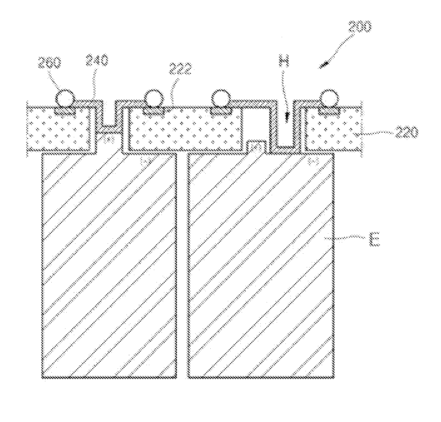
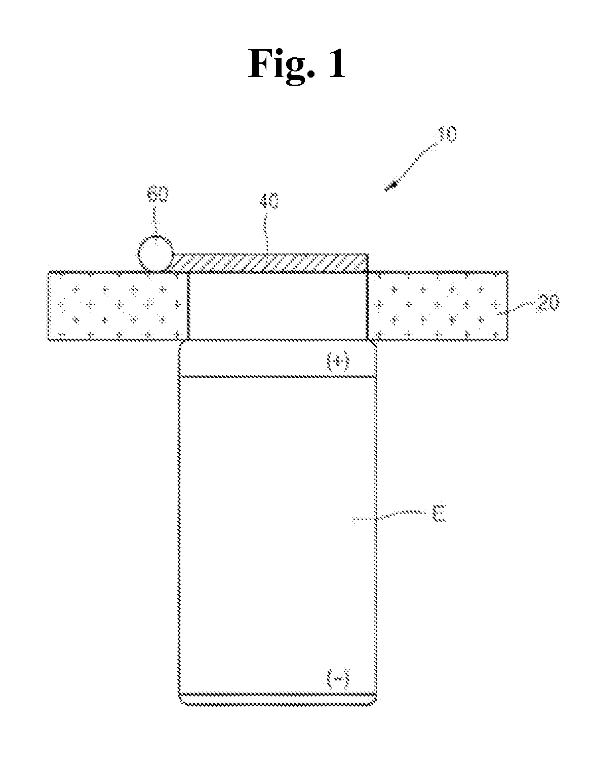
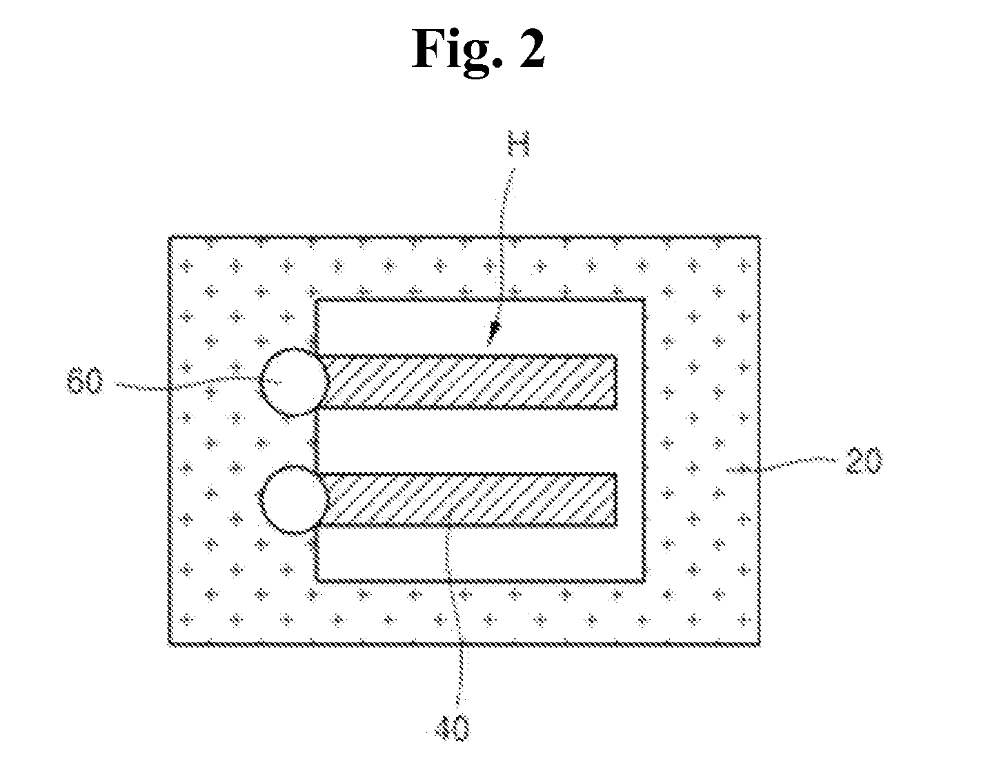
[0028]Hereinafter, a battery assembly with PCB substrate having a bus bar in accordance with exemplary embodiments of the present disclosure will be described with reference to accompanying drawings.

[0029...


PUM

PropertyMeasurementUnit
refractive shapeaaaaaaaaaa
shapeaaaaaaaaaa
electricallyaaaaaaaaaa

Abstract

Disclosed is a battery assembly with a PCB substrate, comprising a bus bar stepped and end processed for enhanced assembly performance and electrical bonding reliability, and a PCB substrate having an assembling groove with an end of the bus bar and an insulating film for an improved stability.

Description

BACKGROUND[0001]1. Technical Field[0002]The present disclosure relates to a battery assembly using a PCB substrate comprising a bus bar, more specifically, to a battery assembly using a PCB substrate comprising a bus bar stepped and end processed for enhanced assembly performance and electrical bonding reliability and a PCB substrate comprising a bus bar having an assembling groove with an end of the bus bar and an insulating film for an improved stability.[0003]2. Description of the Related Art[0004]A conventional bus bar used to connect several battery modules in series or parallel with each other or used to connect safety elements is of a straight-line type, and is connected to the battery through a manual welding. When applying this type of bus bar to a PCB substrate, one end of the bus bar is connected to a surface of the PCB substrate by a soldering process.[0005]FIG. 1 is a cross-sectional view of a PCB substrate having a bus bar according to the prior art.[0006]As seen from ...

Claims


Application Information

Patent Timeline
Patent Type & Authority Applications(United States)
IPC IPC(8): H01M2/20H01M50/505H01M50/51H01M50/512H01M50/519H01M50/583
CPCH01M2/206H01M2/204H01M10/425H01M2200/00Y02E60/10H01M50/519H01M50/583H01M50/512H01M50/51H01M50/505
Inventor SHIN, HYE-WONSON, JUN-HOCHUNG, KWANG-IL
Owner VITZROCELL
Why Eureka
Try Eureka