In-vehicle network system, fraud-detection electronic control unit, and fraud-detection method
a technology of electronic control unit and vehicle body, which is applied in the field of vehicle network system, fraud detection electronic control unit, fraud detection method, etc., can solve problems such as malicious control of vehicle body
- Summary
- Abstract
- Description
- Claims
- Application Information
AI Technical Summary
Benefits of technology
Problems solved by technology
Method used
Image
Examples
first embodiment
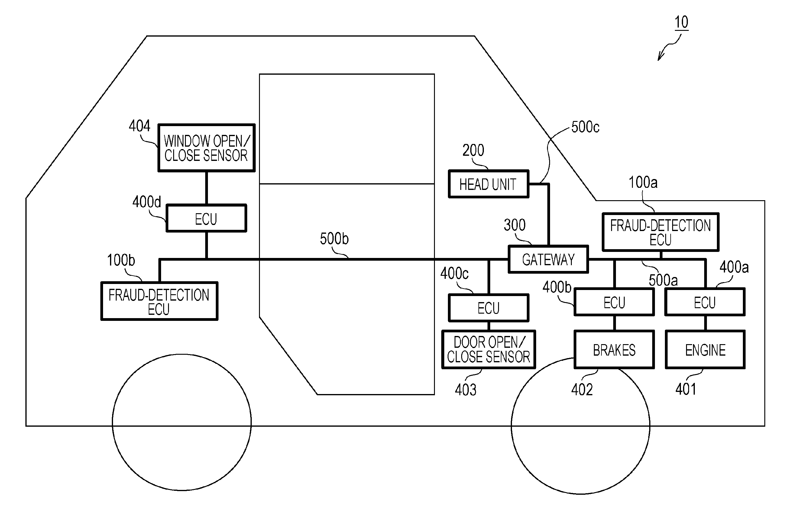
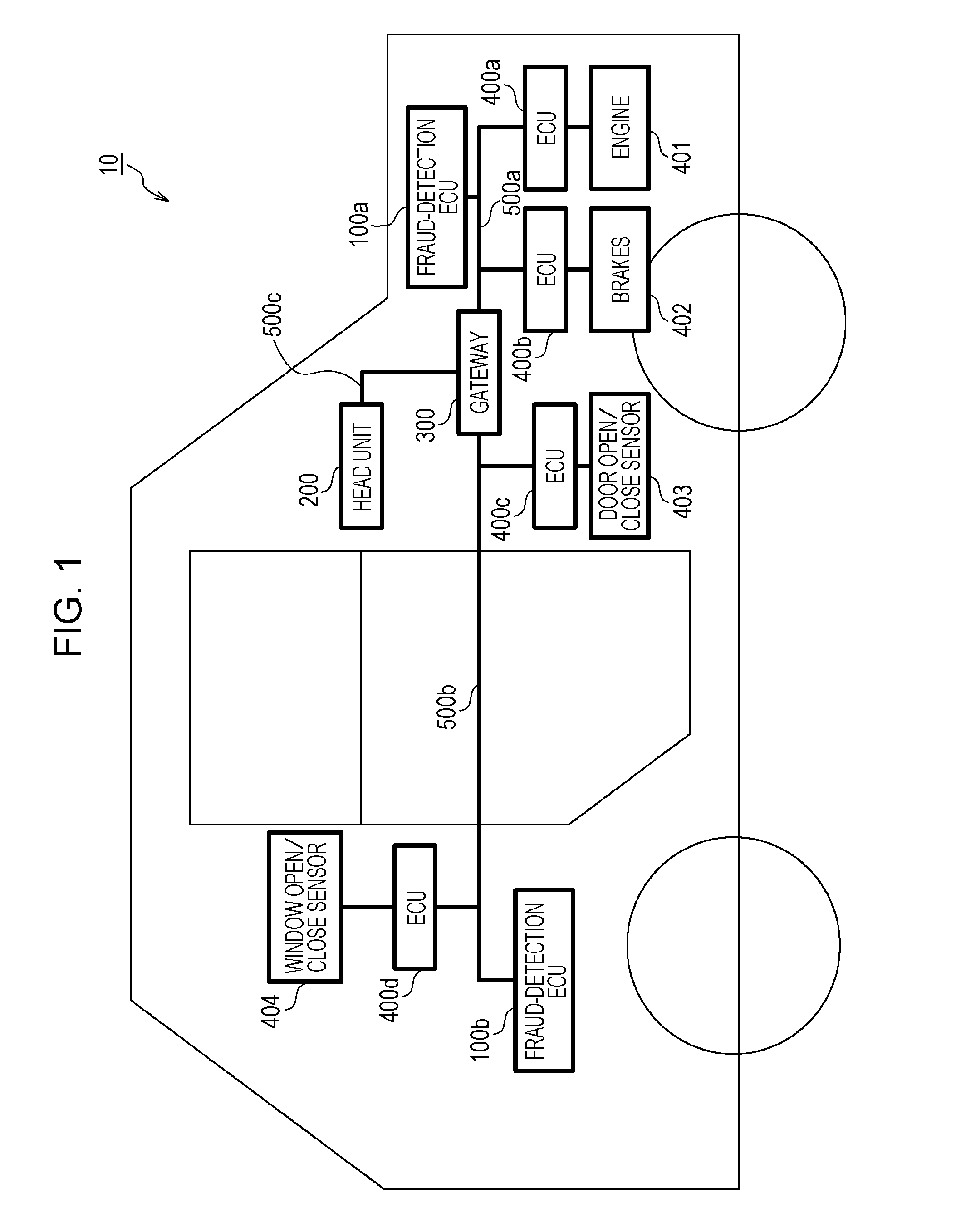
[0067]An embodiment of the present disclosure will now be described with reference to the drawings in the context of an in-vehicle network system 10 including a fraud-detection ECU that implements an anti-fraud method for preventing a process based on a malicious frame from being executed on any other node (ECU) by using a message ID.
1.1 Overall Configuration of In-Vehicle Network System 10
[0068]FIG. 1 is a diagram illustrating an overall configuration of an in-vehicle network system 10 according to a first embodiment. The in-vehicle network system 10 is an example of a network communication system in which communication is performed in accordance with the CAN protocol, and is a network communication system in an automobile provided with various devices such as a control device and a sensor. The in-vehicle network system 10 is configured to include buses 500a to 500c, fraud-detection ECUs 100a and 100b, a head unit 200, a gateway 300, and nodes connected to the buses, called ECUs, s...
second embodiment
[0148]An embodiment of the present disclosure will now be described in the context of an in-vehicle network system 11 including a fraud-detection ECU that implements a fraud-detection method for detecting a malicious frame by using rules for frame transmission which are defined for individual message IDs.
2.1 Overall Configuration of In-Vehicle Network System 11
[0149]FIG. 19 is a diagram illustrating an overall configuration of the in-vehicle network system 11 according to a second embodiment. The in-vehicle network system 11 is obtained by modifying part of the in-vehicle network system 10 illustrated in the first embodiment.
[0150]The in-vehicle network system 11 is configured to include fraud-detection ECUs 2100a to 2100c, a head unit 200, gateways 300 and 300a, and nodes connected to buses, such as ECUs 400a to 400e connected to various devices. Of the constituent elements of the in-vehicle network system 11, constituent elements having functions similar to those in the first embo...
third embodiment
[0172]An embodiment of the present disclosure will now be described in the context of an in-vehicle network system 12 including a fraud-detection ECU that implements a fraud-detection method for detecting a malicious frame by using a frame rule updated in cooperation with a device (an external device) located outside the vehicle.
3.1 Overall Configuration Of In-Vehicle Network System 12
[0173]FIG. 28 is a diagram illustrating an overall configuration of the in-vehicle network system 12 according to a third embodiment. The in-vehicle network system 12 is obtained by modifying part of the in-vehicle network system 11 illustrated in the second embodiment.
[0174]The in-vehicle network system 12 is configured to include fraud-detection ECUs 3100a to 3100c, a head unit 3200, gateways 3300 and 3300a, and nodes connected to buses, such as ECUs 400a to 400e connected to various devices. Of the constituent elements of the in-vehicle network system 12, constituent elements having functions simila...
PUM
 Abstract
Description
Claims
Application Information
 - R&D
- Intellectual Property
- Life Sciences
- Materials
- Tech Scout
- Unparalleled Data Quality
- Higher Quality Content
- 60% Fewer Hallucinations
Browse by: Latest US Patents, China's latest patents, Technical Efficacy Thesaurus, Application Domain, Technology Topic, Popular Technical Reports.
© 2025 PatSnap. All rights reserved.Legal|Privacy policy|Modern Slavery Act Transparency Statement|Sitemap|About US| Contact US: help@patsnap.com


