
System and method for limiting over-voltage in power supply system

a power supply system and over-voltage technology, applied in the field of power supply systems, can solve the problems of difficult to limit the output voltage of the switch mode power supply to a desired voltage level, the efficiency of the transformer often varies with the electrical, and the transformer is often big, heavy,

Active Publication Date: 2017-02-02
OTIS ELEVATOR CO
View PDF33 Cites 1 Cited by
  • Summary
  • Abstract
  • Description
  • Claims
  • Application Information

AI Technical Summary

Benefits of technology

The patent aims to prevent the output voltage from going over 60 volts of direct current. This is achieved through the use of two voltage monitors. The technical effect of this is to ensure the safe and reliable operation of electrical equipment.

Problems solved by technology

However, the efficiency of the transformer often varies with the electrical load, going down, sometimes significantly, at standby operation of the elevator system.
Further, transformers are often big, heavy, and costly to operate and maintain.
However, unlike a traditional transformer, the output voltage from the switch mode power supply may be difficult to limit to a desired voltage level.

Method used


Image

  • System and method for limiting over-voltage in power supply system
  • System and method for limiting over-voltage in power supply system
  • System and method for limiting over-voltage in power supply system

Examples


Embodiment Construction

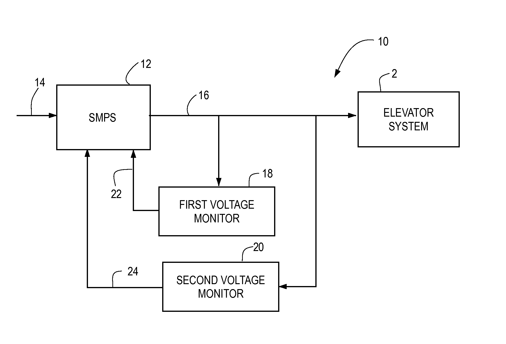
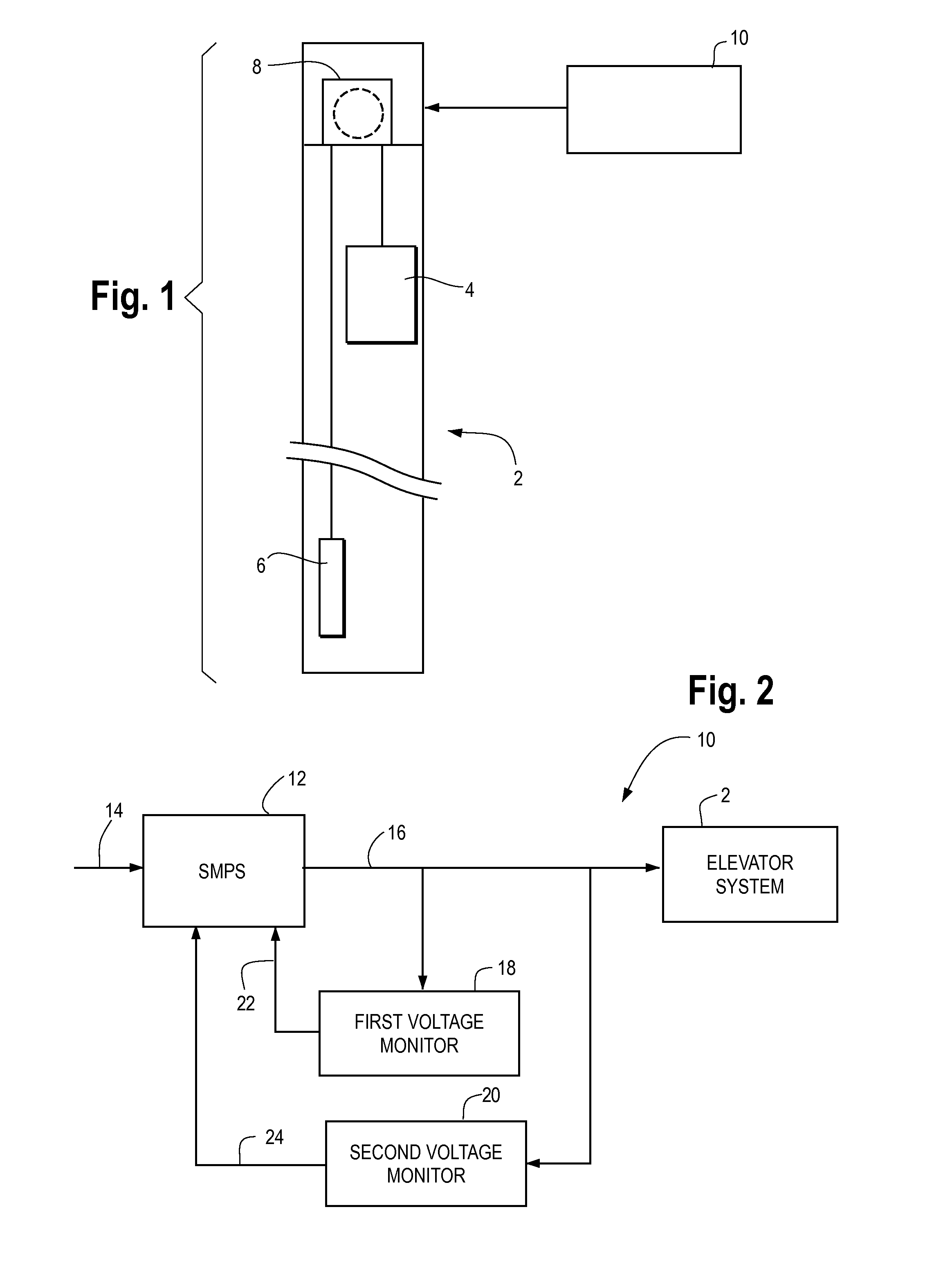
[0028]Referring now to FIG. 1, a simplified schematic diagram of an elevator system 2 is shown, in accordance with at least some embodiments of the present disclosure. While all of the components of the elevator system 2 have not been shown and / or described herein, a typical elevator system may include an elevator car 4 connected to a counterweight 6 via hoisting ropes, not shown. In at least some embodiments, the hoisting ropes may extend over a traction sheave 8 driven by an electric motor within the traction sheave to move or halt the elevator car 4 as desired. The elevator system 2, with the counterweight 6, may operate in a known manner and therefore, the operation of the elevator system is not described in detail herein. The elevator system 2 may also include a power supply system 10 for providing power to the various components of the elevator system, such as the electric motor, the elevator car 4, etc. The power supply system 10 may receive power from a main power source, su...


PUM


Abstract

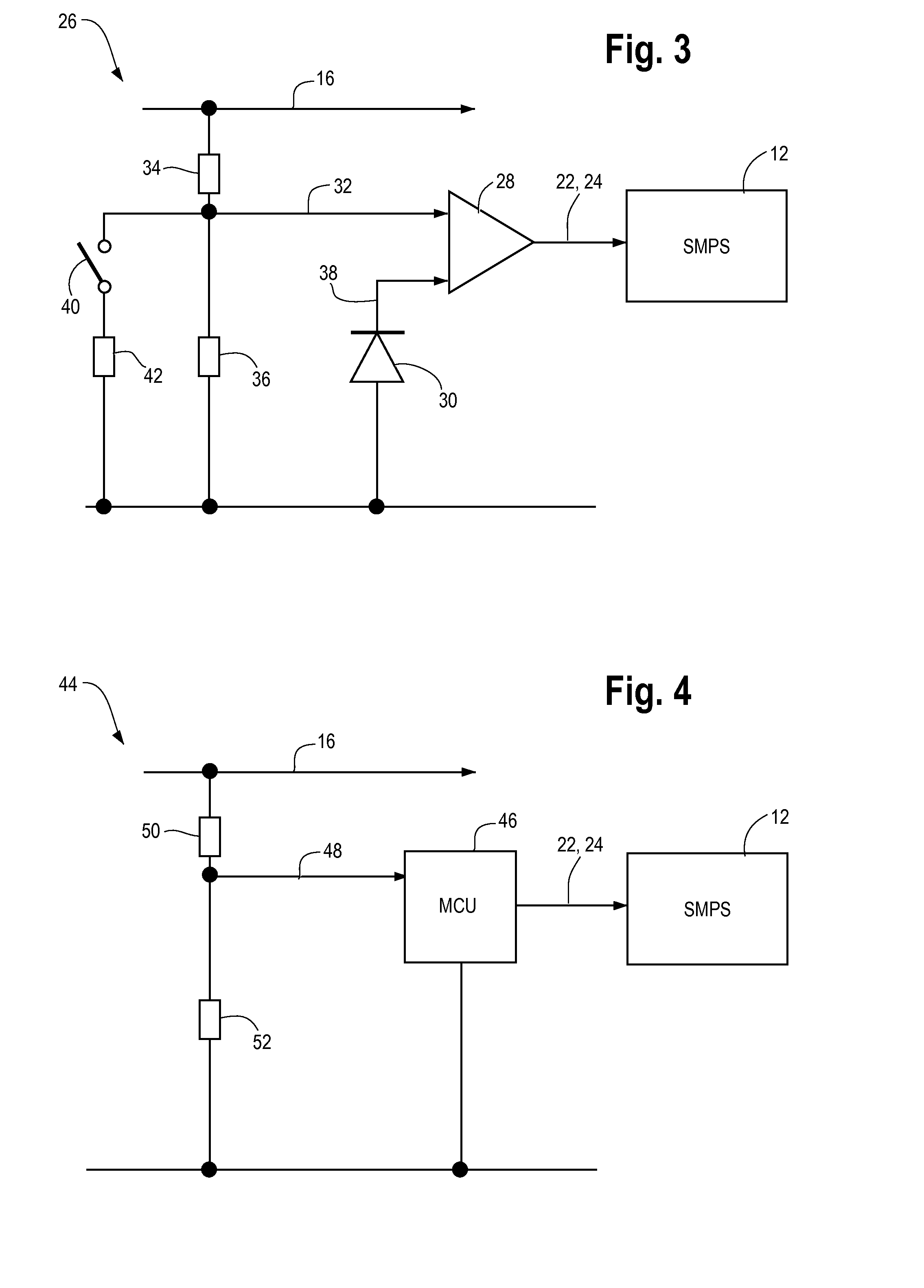
A system and method for providing a protective extra low voltage power supply in an elevator system (2) is disclosed. The power supply system (10) may include a switch mode power supply (12) configured to provide an output voltage, a first voltage monitor (18) and a second voltage monitor (20). Each of the first voltage monitor (18) and the second voltage monitor (20) may be configured to receive the output voltage and determine an over-voltage condition at the switch mode power supply (12).

Description

FIELD OF THE DISCLOSURE[0001]The present disclosure relates generally to power supply systems and, more particularly, relates to a system and method for limiting over-voltage conditions in power supply systems.BACKGROUND OF THE DISCLOSURE[0002]Elevator systems are widely used for transporting people or goods from one point to another. An elevator system typically includes an elevator car connected to a counterweight by hoisting ropes that move the elevator car vertically in an elevator shaft or hoistway. The hoisting ropes extend over a sheave or machine. A motor connected to the machine provides power to move the elevator car between two positions. The machine (and specifically the motor of the machine) is provided with a brake system to control the motion of the elevator car and to stop the elevator car as desired. The elevator car, motor, brake system, and other electrical components of the elevator system are supplied power via a power supply system connected at least indirectly...

Claims


Application Information

Patent Timeline
Patent Type & Authority Applications(United States)
IPC IPC(8): B66B1/30B66B1/34G01R19/165B66B5/00
CPCB66B1/30B66B5/0031B66B9/00B66B5/0087G01R19/165B66B1/3446B66B1/28
Inventor GEWINNER, JUERGENHERKEL, PETER
Owner OTIS ELEVATOR CO
Learn More